air feed / rapid master with keypad operating instructions Rapid-air corporation 4601 Kishwaukee St. • Rockford, IL 61109-2925 Phone: (815) 397-2578 • Fax: (815) 398-3887 • Web Site: www.rapidair.
table of contents INSTALLATION AND MECHANICAL SET-Up of die or punch......................................................... pg. 3 air feed progression SET-UP AND MAINTENANCE...................................................................... pg. 4 LUBRICATION............................................................................................................................................... pg. 5 electrical SET-UP, PRETEST AND LOADING material....................................................
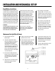
installation and mechanical set-up Rapid Master Installation The Rapid Master that you have just received is fully assembled and ready to be put into production. Due to shipment vibration and handling, the machine should be checked to ensure all screws and bolts are tight. Remove the cover to the electrical controls and visually inspect that all parts are in place and secure. If the machine was damaged in shipment, contact the carrier first to report the damage and then Rapid-Air.
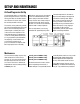
Set-up and maintenance Air Feed Progression Set-Up The feed guide rollers are adjustable by loosening the machine screws and moving the rollers to the desired position. For best result, the stock should be centrally located in the feed. The notches in the guide rails provide for coarse feed adjustment of the stop block. The final feed adjustment for stroke length is made by the screw in the center of the stop block.
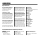
lubrication Proper Lubrication For a general guide for the Rapid Master, the lubricator oil release adjustment should be set to one drop of oil for each 50-80 strokes. (See insert on lubrication of “O” rings.) 170 S.S.U., the API gravity 29.5 minimum and the aniline point between 150 F and 210 F. Variation of the aniline point from the limits given is likely to cause either shrinkage or stretching of the “O” rings.
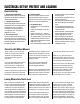
electrical set-up, pretest and loading Electrical Set-Up 1. Master power on/off button Lighted 2 position switch, located on the side of the console. When turned on the switch should illuminate. 2. Tonnage selector switch The tonnage selector switch selects the Rapid Master ram force exerted. On the side of the ram units is a 2 position, screwdriver slot, selector switch to accomplish this task. The switch is labeled 2 ton or 4 ton. 3.
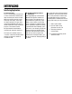
interfacing Interfacing Explanation A. Taut stock input This is a normally open contact from a switch or device that monitors the loop of material prior to the air feed. When the material reaches a point that it trips the switch, a taut stock has been reached. This input, when received, immediately drops the automatic mode which stops the feed in progress. The material should be repositioned in the die before restarting the automatic sequence.
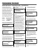
programming procedure Operator Input Terminal – Programming Procedure – Standard Software The intent of this section is to familiarize the operator with the program flow and what to expect with every keypress. Each screen on the display will be reviewed with special comments to help clarify what is being asked on the screen. The program flow is broken down into sections with the main menu being the home position. Reviewing the flow chart in the back of this manual will help in understanding the sections.
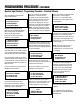
programming procedure (continued) Operator Input Terminal – Programming Procedure – Standard Software Press the F4 exit key until the main menu screen appears. Feed cycles/cut=XX F1=Set Cycle per Cut F2=Manual Mode F3=Automatic Mode We have covered all the setup operations of the Air/Rapid Master. Now we will cover the automatic portion of the programming. Press the F3 “Auto” key and the following screen appears.
troubleshooting electrics Problem Possible Cause Remedy The attempt is made to start the machine by pulling the mushroom start button but no lights illuminate. – No power at source. – Check building for recpt. for voltage. – The machine is not plugged into the source power. – Plug cord into 120 volt - 1 PH recept. – Fuse blown on the control. – Look for burn spots to see what caused the blown fuse – replace fuse. – Loose wiring. – Inspect wiring to terminals for loose wires or loose screws.
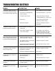
Characteristics and possible causes of troubles with rapid-air feeds Problem Possible Causes Remedy Feed and stock clamps work, but slide block does not move when actuating valve is depressed. – Pilot operated valve is stuck. – Check for grit, swollen nylon or swollen “O” rings. Excessive leakage of air from exhaust hole beneath speed adjusting screw when actuating valve is in up position. – Poppet not seating on bottom of valve hole. – Check for grit or chips.
Characteristics and possible causes of troubles with rapid-air feeds (continued) Problem Possible Causes Remedy Cushion pistons act too slow and provide too much cushion. – Excessive oil, reduce supply. – Adjust air / oil mixture. Mist of oil coming from exhaust hole. – Excessive oil, reduce supply. – Adjust air / oil mixture. Feed has difficulty pushing last part of progression. – Feed is not inline with die.
Characteristics and possible causes of troubles with rapid-air feeds (continued) Problem Possible Causes Remedy Slide block will move out okay, but will not return without hesitation. – Check speed adjusting screw. – Adjust for smooth operation. – Check pilot operated valve. Swollen “O” ring could be binding, until pressure build up breaks it free. Check poppet valve. – Check moisture content in air lines. Change “O” rings. Feed acts sluggish on start up. Okay after running for awhile.
14 Programming Procedure
15 Programming Procedure
16 Air Feed Speed Adjustment
17 Programming Procedure
18 Electrical Assembly
19 Operator Keypad
20 Control Panel Wiring Diagram
21 Rapid Master Unit with Air Feed
22 Rapid Master Mechanical Setup
warranty Warranty Terms & Conditions All sales by the company are made subject to the following terms and conditions. please read. WARRANTY – The Company warrants, for a period of one year from date of shipment by the Company, that the product shipped is free from defects in material and workmanship. THIS WARRANTY IS EXCLUSIVE AND IN LIEU OF ALL IMPLIED WARRANTIES IN LAW, INCLUDING MERCHANT - ABILITY. The Company obligation under this warranty is limited to repairing or replacing, F.O.B.