SERVO FEED – GAG FEED PROGRAM OPERATING INSTRUCTIONS MODELS 200 & 300 SERIES RAPID-AIR CORPORATION 4601 KISHWAUKEE ST. • ROCKFORD, IL 61109-2925 Phone: (815) 397-2578 • Fax: (815) 398-3887 • Web Site: www.rapidair.
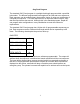
Gag Feed Program The standard “GAG” feed program is a multiple feed length program within a specified job number. The different programmed feed lengths will be referrred to as sequences. Each sequence can be repeated many times with a choice of using any combination of 8 outputs per sequence . For each output there is an input that can be used to verify that the output device has moved.
RAPID-AIR ONE DAY START UP AND TRAINING SECTION (200-300 series only) Congratulations on purchasing a Rapid-Air Servo. Not only did you receive a complete servo unit but also a one day start up and training by one of our engineering staff to guide you on using the new servo to it’s maximum capability. In order to maximize your learning time and trouble shoot any interface problems.
TABLE OF CONTENTS CHARTS AND DRAWINGS DIRECTORY pg. 4 INTRODUCTION pg. 5 INSTALLATION AND MECHANICAL SETUP pg. 6 INSTALLATION OF MOUNTING BRACKET pg. 7 MECHANICAL ROLL RELEASE SETUP pg. 8 ELECTRICAL CABLES AND AIR LINE pg. 9 INTERFACING FEED WITH PRESS pg. 10 PRETEST WRITE UP pg. 11 LOADING MATERIAL pg. 12 SERVO INTERFACING EXPLANATION pg. 13-14 PROGRAMMING PROCEDURE pg. 15 DRIVE ROLL PARALLELISM ADJ. pg. 23 TROUBLESHOOTING pg. 24-25 OPERATIONAL MAINTENANCE PROCEDURES pg.
CHARTS AND DRAWINGS PLAN 100 SERIES pg. 30 PLAN 200 SERIES pg. 31 PLAN 300 SERIES pg. 32 SERVO BRACKET SIDE 100 SERIES 200/300 SERIES - 4&8” pg. 33 pg. 34 ELECTRICAL PANEL LAYOUT pg. 35 OPERATORS TERMINAL LAYOUT pg. 36 PROGRAMMING MAP pg. 37 JOB INPUT SEQUENCE pg. 38 MANUAL SEQUENCE pg. 39 AUTOMATIC SEQUENCE pg. 40 STROKES PER MINUTE VS. FEED WINDOW pg. 41 PRESS-FEED AND PILOT SWITCH SETTINGS pg. 42 INTERFACE SCHEMATICS - 752 pg. 43 INTERFACE SCHEMATICS - 753 pg.
INTRODUCTION The Rapid-Air Servo feed carries with it the quality and reliability you have grown to expect from a Rapid-Air product. The motion control system is a programmable industrial computer and this advanced technology married to a highly engineering precision roll feed, is an unchallanged combination in the stamping industry. The compact mechanical package, direct coupled with a brushless servo drive motor, offers response and feed accuracies unparalled in any other powered roll feed.
INSTALLATION AND MECHANICAL SETUP OF SERVO FEED The shipping container should contain: 1 Mechanical Servo Feed -Standard 1 Console Complete -Standard 1 Cascade Assembly -Optional (100 Series) (Standard 200-300 Series) 1 Servo Mounting Bracket -Optional 1 Guide Support Assy. -Optional If a mounting bracket was purchased then it should be installed at this time.
INSTALLATION AND MECHANICAL SETUP OF MOUNTING BRACKET The cast mounting bracket is available for mounting the servo feed directly to the bolster plate of the press. There are several sets of mounting holes in the bracket to afford the setup person an efficient means of mounting the bracket. Mounting holes are located on the top and front for securing the bracket firmly. It is very important that the servo bracket and the servo feed be secured and not allowed to float or vibrate.
MECHANICAL ROLL RELEASE SETUP All Rapid-Air feeds are supplied with a manual pilot release. If the manual pilot release is used, and we recommend this for press speeds faster than 250 SPM, then a bracket has to be manufactured and attached to the press ram to actuate the pilot release mechanism. (Note: The roll release height adjustment screw should be backed off all the way to prevent jamming when using the mechanical release.
ELECTRICAL CABLES AND AIR LINE 230 VAC INPUT The required input voltage to the control is 230 Vac, 3 Ph, 60 Hz. The amperage needed is 6 amps for 752 control and 10 amps for the 753 control. If unsure of the amperage needed, the name plate on the side of the Pacific Scientific drive will give the number of the control or check the disconnect fuses for the correct fuse size. 460 VAC INPUT If your plant has only 460 Vac power then a step down transformer is needed in order to run the servo feed.
INTERFACING SERVO FEED WITH A PRESS The Servo Drive unit is a slave to the press therefore it needs a command from the press to operate in the automatic mode. The command is in the form of a normally open contact from a limit switch, cam switch or an electronic feed interface device that can be programmed. The contact should be commanded or activated at 270 degrees of the press stroke or when the tooling is clear of the material and released or turned off at around 350 degrees of the press stroke.
PRETEST FOR SERVO FEED AND PRESS WITHOUT MATERIAL Now that your servo feed unit has been mounted and the cables have been attached, you can proceed with testing the unit. The first step is to turn on the main disconnect switch on the electrical enclosure. Next, at the operator’s console, pull the power onoff button to the on position. The button should illuminate to indicate that there is power to the system. The Pacific Scientific drive preforms an initiate sequence to check it’s internal program.
LOADING MATERIAL INTO THE SERVO FEED Upon the satisfactory completion of all the tests, you should be ready to load a strip of material into the servo feed. Step number one is to select the manual mode of operation on the operators console. Then choose “Operate Rolls”. This will allow you to open the feed rolls and antibackup rolls to accept the material. You could also open the rolls manually by turning the levers mounted on the side of the servo feed.
SERVO INTERFACING EXPLANATION A. TAUT STOCK INPUT (J55-3) This is a normally open contact from a switch or device that monitors the loop of material prior to the servo feed. When the material reaches a point that it trips the switch, a taut stock has been reached. This input, when received, immediately drops the automatic which stops the feed in progress. The material should be repositioned in the die before restarting the automtaic sequence.
D. GAG OUPUTS (J53-6 to J53-9) & (J54-2 to J54-5) This output must be tied to a solid state relay to interface to the outside world. The solid state relay must have a D.C. coil and should have a rating of 3-30 VDC. The Rapid-Air #69100165 is recommended for this application. This output is high whenever the enabled input is activated. If using DC coils then 3-30 VDC sink, max 100 MA, per output. E. END OF FEED OUTPUT (J54-6) This output must be tied to a solid state relay to interface to the outside world.
OPERATOR INPUT TERMINAL - PROGRAMMING PROCEDURE-STANDARD SOFTWARE The intent of this section is to familiarize the operator with the program flow and what to expect with every keypress. Each screen on the display will be reviewed with special comments to help clarify what is being asked on the screen. The program flow is broken down into 5 sections with the main menu being the home postion. Reviewing the flow chart in the back of this manual will help in understanding the sections.
The job number screen displays (2) choices for the operator. In the first choice, F1=Program new values, the operator can enter or change the number of sequences, repeats per sequence, pilots, feed length, strokes per minute that the press is running and feed arc angle. (Free travel of the press in which the feed can move material without a problem) this then calculates the optimum speed of the material movement.
After pressing the F4 key and the parameters are within the operating range, the following screen appears. JOB#=00 SEQUENCE=00 FL=000.000 REPEAT=00 OUTPUTS=000 PILOTS=0 PRESS ENTER FOR NEXT This screen will repeat for all the sequences selected. Press enter key to move from FL, repeat, outputs and pilots. Press F4 key when all sequence parameters have been entered. When complete, the main menu will appear.
Pressing the F4 key once will reset the program to the jog mode screen so that jog is now active. Pressing the F4 key twice will reset the program to the manual mode screen. If the F4 key was pressed twice then the following screen is displayed MANUAL MODE F1=INCH F2=SINGLE FEED MODE F4=EXIT MANUAL MODE CYCLE ROLL WITH KEYS F2=SINGLE FEED If the operator presses F2 then the following screen is displayed.
If the F2 key was pressed then the servo will be in the auto total mode and the following screen appears. AUTOMATIC FL=000.000 JOB #=00 SEQ=00 REP=00 TOTAL COUNTER=000000 F4=EXIT AUTO CYCLE Pressing the F4 key, stops the automatic cycle and the main menu screen appears.
Pressing the F4 key, stops the automatic cycle and the main menu screen appears. When the automatic screen is displayed, all keys except the F4 key are inactive. Every time the press cycles and trips the feed switch, the feed will cycle once per the parameters displayed on the screen. If the feed encounters excessive materail drag while feeding or the material being moved encounters a restriction taht stops the material forward movement then a servo fault can occur.
sequence, like a length change, then the length could be adjusted now and the sequence would be changed in the job memory for any future running of the job. The repeats, outputs, pilots, speed and accel can also be adjusted at this time. When finished, press the F4 key and the main menu screen will be displayed. The last section to be covered is the ramp/counters section. To get into this mode, press the ramp pushbutton and the following screen appears.
ENTER ACCEL RAMP % MAX%=75000 RPM/SEC MAXIMUM ACCEL %=002% F4=EXIT (RAMP MENU) JOB NUMB=00 ENTER IN PERCENT MAX VEL=000% PRESS F4 KEY ONCE CORRECT # IS ENTERED 22
DRIVE ROLL PARALLELISM ADJUSTMENT Every servo feed has an eccentric adjustment screw to adjust the upper roller to be in parallel to the lower roller. The maximum adjustment is .008” on the eccentric. The adjustment screw is located behind the belt cover and is held fast by a 10-32 socket head cap screw. The acutal adjustment screw is a slotted eccentric pin which is turned clockwise or counter-clockwise to raise or lower one end of the upper roll.
PROBLEM TROUBLESHOOTING CHART CAUSE REMEDY No power indication Disconnect off Blown fuse Master button in Turn disconnect on Check/replace fuse Pull button out No display on operators console Program fault Faulty wiring Check lights on drive Check plug on console Power on-no motion Program fault Drive fault Program error Check lights on drive Check lights on drive Check parameters No roll action No air Low air pressure Check air line Check air regulator Material will not enter rolls Anti-back
PROBLEM Material feeds off center No automatic cycle TROUBLESHOOTING CHART (cont.) CAUSE REMEDY Edge guides not set properly Material not centered in feed No press signal Controller fault Servo fault Program error Set edge guides Center material Check limit switch input to servo control Check lights on P.C.
MOTOR SERVICE The servo motor is flanged mounted and secured with four socket head cap screws. The motor removal has to be done in a sequence as described below. 1. The manual roll release handle has to be removed. The inner roll pin holds the handle to the shaft. Once this is removed the handle should slide off the shaft. 2. The belt guard has to be removed. It is fastened with four 1/4-20 socket head cap screws. 3. Remove the belt tension and then the belt sheave has to be removed.
REASSEMBLY OF UNIT Prior to assembly, attention must be given to three points of contact that require an application of Moly-Cote, Lubriplate or other suitable heavy grease. The three points are: 1. The antibackup piston which is located at the feed entrance. 2. The main roll piston and the spiral pins in the main roller tie plate which can be seen by viewing straight down through the center of the feed at approximately half way from the inlet to the exit roller.
PRECAUTIONS & SAFETY NEVER - Put screwdrivers or foreign materials in feed rolls NEVER - Hold onto material as it is being fed through the servo NEVER - Wear neckties around the servo feed rolls NEVER - Force the rolls open by prying on them NEVER - Modify the mechanical aspects of the servo feed CAUTION - Contact the factory before drilling any holes in the unit CAUTION - Wear proper eye protection when working around the servo CAUTION - Do not wear loose clothing around the servo feed rolls 28
WARRANTY ALL SALES BY THE COMPANY ARE MADE SUBJECT TO THE FOLLOWING TERMS AND CONDITIONS. PLEASE READ. WARRANTY - The Company warrants, for a period of one year from date of shipment by the Company, that the product shipped is free from defects in material and workmanship. THIS WARRANTY IS EXCLUSIVE AND IN LIEU OF ALL IMPLIED WARRANTIES IN LAW, INCLUDING MERCHANT - ABILITY. The Company obligation under this warranty is limited to repairing or replacing, F.O.B.
30
31