servo feed / rapid master operating instructions Rapid-air corporation 4601 Kishwaukee St. • Rockford, IL 61109-2925 Phone: (815) 397-2578 • Fax: (815) 398-3887 • Web Site: www.rapidair.
table of contents INTRODUCTION........................................................................................................................................... pg. 3 INSTALLATION, SET-UP, AND CABLING.................................................................................................. pg. 4 PRETEST........................................................................................................................................................ pg. 5 INTERFACING.....................
introduction The Rapid Master The Rapid Master that you have just received is fully assembled and ready to be put into production. Due to shipment vibration and handling, the machine should be checked to ensure all screws and bolts are tight. Remove the cover to the electrical controls and visually inspect that all parts are in place and secure. If the machine was damaged in shipment, contact the carrier first to report the damage and then Rapid-Air.
installation, set-up, and cabling Installation And Mechanical Set-Up Of Servo And Press If you purchased the Servo/Rapid Master combination already mounted on a base then the servo and press were aligned at the factory. A good practice is to check all hold down bolts to be sure that they did not come loose during shipment.
pretest Pretest For Servo Feed And Press Without Material Now that your servo/press combination is in place, and the cables have have been attached, you can proceed with testing the unit. The first step is to turn on the main disconnect switch on the electrical enclosure. Next, at the operator’s console, pull the power on-off button to the on position. The button should illuminate to indicate that there is power to the system.
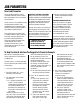
interfacing Servo Interfacing Explanation A. TAUT STOCK INPUT (J52)TBI-3) This is a normally open contact from a switch or device that monitors the loop of material prior to the servo feed. When the material reaches a point that it trips the switch, a taut stock has been reached. This input, when received, immediately drops the automatic which stops the feed in progress.
job parameters Reset Job Parameters The reset job parameters routing should be used with special caution. We incorporated it as a user function for two reasons. The first reason is if a problem caused the displayed parameters to be garbled because of a program glitch, then by resetting the job parameters the problem could be cleared.
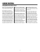
Loading material Loading Material Into The Servo Feed Upon the satisfactory completion of all the tests, you should be ready to load a strip of material into the servo feed. Step number one is to select the manual mode of operation on the operators console. Then choose “Operate Rolls”. This will allow you to open the feed rolls and anti-backup rolls to accept the material but only if you have purchased the option.
programming procedure Operator Input Terminal – Programming Procedure – Standard Software The intent of this section is to familiarize the operator with the program flow and what to expect with every keypress. Each screen on the display will be reviewed with special comments to help clarify what is being asked on the screen. The program flow is broken down into 5 sections with the main menu being the home position.
programming procedure (continued) Operator Input Terminal – Programming Procedure – Standard Software MANUAL MODE F1=INCH F2=SINGLE FEED MODE F4=EXIT MANUAL MODE CYCLE ROLL WITH KEYS F2=SINGLE FEED If the operator presses F2 then the following screen is displayed. The single feed mode is active and every time the F1 key is pressed then the feed will cycle and move the distance indicated on the feed length line. JOB#=00 FL=000.
programming procedure (continued) Operator Input Terminal – Programming Procedure – Standard Software The last section to be covered is the ramp/counters section. To get into this mode, press the ramp push-button and the following screen appears. SELECT RAMP/COUNTERS F1=BATCH/TOTAL COUNT F2=ACCEL/DECEL RAMPS F4=EXIT TO MAIN MENU F1 =BATCH/TOTAL COUNTS Pressing the F1 key will bring up the batch/total screen, which is used for presetting the batch count or resetting the total count.
parallelism Drive Roll Parallelism Adjustment Every servo feed has an eccentric adjustment screw to adjust the upper roller to be in parallel to the lower roller. The maximum adjustment is .008” on the eccentric. 2. Raise the anti-backup rolls. (If any) main rolls should be closed. The adjustment screw is located behind the belt cover and is held fast by a 10-32 socket head cap screw.
troubleshooting Problem Cause Remedy No power indication No display on operators console Power on – no motion No roll action Material will not enter rolls Material will not feed Material feeds short Material feeds long Material camber – Disconnect off – Turn disconnect on – Blown fuse – Check / replace fuse – Master button in – Pull button out – Program fault – Check lights on P.C.
troubleshooting (continued) Problem Cause Remedy Material feeds off center No automatic cycle Servo hum Fault signal on Pac-Sci is displayed Cannot program unit from display Mechanical pilot release sticks down – Edge guides not set properly – Set edge guides – Material not centered to feed – Center material – Bad material – Try new roll of material – No press signal – Check limit switch input to servo control – Con
MOTOR service AND FAULT DISPLAY Servo Motor Service The servo motor is flanged mounted and secured with four socket head cap screws. The motor removal has to be done in a sequence as described below. 1. 2. 3. 4. 5. The manual roll release handle has to be removed. The inner roll pin holds the handle to the shaft. Once this is removed the handle should slide off the shaft. The belt guard has to be removed.
troubleshooting Fault Code (Predefined Variable, Integer, Status Variable, Read-Only) Guidelines - 0 means the drive is not faulted and not enabled, while 8 means the drive is not faulted and enabled. Alternating 8.> means actively inhibiting CW motion and alternating 8.
reassembly and lubrication Reassembly Of Unit Prior to assembly, attention must be given to three points of contact that require an application of Moly-Cote, Lubriplate or other suitable heavy grease. The three points are: 1. The antibackup piston which is located at the feed entrance. 2. The main roll piston and the spiral pins in the main roller tie plate which can be seen by 3.
Precautions & safety Precautions & safety NEVER – NEVER – NEVER – NEVER – NEVER – CAUTION – CAUTION – CAUTION – Put screwdrivers or foreign materials in feed rolls Hold onto material as it is being fed through the servo Wear neckties around the servo feed rolls Force the rolls open by prying on them Modify the mechanical aspects of the servo feed Contact the factory before drilling any holes in the unit Wear proper eye protection when working around the servo Do not wear loose clothing around the servo fee
warranty Warranty Terms & Conditions All sales by the company are made subject to the following terms and conditions. please read. WARRANTY – The Company warrants, for a period of one year from date of shipment by the Company, that the product shipped is free from defects in material and workmanship. THIS WARRANTY IS EXCLUSIVE AND IN LIEU OF ALL IMPLIED WARRANTIES IN LAW, INCLUDING MERCHANT - ABILITY. The Company obligation under this warranty is limited to repairing or replacing, F.O.B.
20 Rapid-Master/106 Servo CTL
Set-Up Mechanical Set-Up Of Die Or Punch 1) Secure the die set to the bolster plate. 2) The piston adjustment sleeve (item #1), establishes the stroke to a maximum of .50 inches when fully extended. The stroke is reduced by 1.8 inches with each full inward rotation, using the 3-3/4 spanner wrench provided. The piston stroke adjustment sleeve is locked in place with a nylon tipped set screw (item #2).
22 Electrical Schematic
23 Keypad ** Keypad shown with all options . Left 2 rows may vary depending on options purchased.
24 100 Series Rapid Master – SC953 Servo Wiring Diagram
25 Inter-Connect Wiring Diagram
26