SERVO FEED WITH CUT-TO-LENGTH OPERATING INSTRUCTIONS MODELS 100, 200 & 300 SERIES RAPID-AIR CORPORATION 4601 KISHWAUKEE ST. • ROCKFORD, IL 61109-2925 Phone: (815) 397-2578 • Fax: (815) 398-3887 • Web Site: www.rapidair.
1
RAPID-AIR START UP SECTION SERVO FEED—CUT TO LENGTH 100, 200, 300 Series Rev. C Congratulations on purchasing a Rapid-Air Servo Cut-To-Length. Not only did you receive a complete servo unit but also telephone support by one of our engineering staff to guide you on using the new servo to its maximum capability. In order to maximize your learning time and trouble shoot any interface problems, we would like to request that the following items be complete before calling us: 1.
TABLE OF CONTENTS CHARTS AND DRAWINGS DIRECTORY pg. 4 INTRODUCTION pg. 5 INSTALLATION pg. 6 ELECTRICAL CABLES AND AIR LINE pg. 7 INTERFACING SERVO FEED WITH CUTTER pg. 8 PRETEST WRITE UP pg. 9 LOADING MATERIAL pg. 10 SERVO INTERFACING EXPLANATION pg. 11 PROGRAMMING PROCEDURE pg. 15 DRIVE ROLL PARALLELISM ADJ. pg. 21 TROUBLESHOOTING pg. 22 OPERATIONAL MAINTENANCE PROCEDURES pg. 24 PRECAUTIONS AND SAFETY pg. 28 WARRANTY pg.
CHARTS AND DRAWINGS PLAN 100 SERIES pg. 30 PLAN 200 SERIES pg. 31 PLAN 300 SERIES pg. 32 ELECTRICAL PANEL LAYOUT pg. 33 OPERATORS TERMINAL LAYOUT pg. 34 INTERFACE SCHEMATICS - 953 pg. 35 INTERFACE SCHEMATICS - 953 pg 36 INTERFACE SCHEMATICS– 953 120 VAC pg 37 CUTTER MAINTENANCE pg. 38 CUTTER BASE LAYOUTS pg.
INTRODUCTION The Rapid Air Servo Cut-To-Length Feed system carries with it the quality and reliability you have grown to expect from a Rapid Air product. The motion control system is a programmable industrial computer and this advanced technology, combined with a highly engineered precision roll feed, is an unchallenged combination in the press industry.
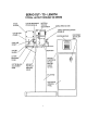
INSTALLATION AND MECHANICAL SETUP OF SERVO AND CUTTER If you purchased the servo/cutter combination already mounted on a base then the servo and cutter were aligned at the factory. A good practice is to check all hold down bolts to be sure that they did not come loose during shipment.
ELECTRICAL CABLES AND AIR LINE 120 VAC INPUT The alternate input voltage to the control is 120 Vac, 1 Ph, 60 Hz. The max amperage needed is 7.5 amps and the control has a circuit breaker with a trip amperage of 10 amps.. 230 VAC INPUT The required input voltage to the control is 230 Vac, 3 Ph, 60 Hz. The amperage needed is 10-20 amps depending on the motor size.
INTERFACING SERVO FEED WITH A CUTTER The Servo Drive unit is programmed to feed each time a signal is received from the cutter switch. The servo will feed one progression and wait for the next signal before it will feed again in automatic mode. The command is in the form of a normally open contact from a proximity switch, located on the cutter and is activated when the cutter is returned. If the feed/cutter was purchased complete then the interfacing was done for you.
PRETEST FOR SERVO FEED AND CUTTER WITHOUT MATERIAL Now that your servo/cutter combination is in place, and the cables have been attached, you can proceed with testing the unit. The first step is to turn on the main disconnect switch on the electrical enclosure. Next, at the operator’s console, pull the power onoff button to the on position. The button should illuminate to indicate that there is power to the system. The Pacific Scientific drive performs an initial sequence to check its internal program.
LOADING MATERIAL INTO THE SERVO FEED Upon the satisfactory completion of all the tests, you should be ready to load a strip of material into the servo feed. Step number one is to select the manual mode of operation on the operators console. Then choose “Operate Rolls”. This will allow you to open the feed rolls and antibackup rolls to accept the material but only if you have purchased the option. You could also open the rolls manually by lifting the lever mounted on the side of the servo feed.
SERVO INTERFACING EXPLANATION A. TAUT STOCK INPUT (J52)TBI-3) This is a normally open contact from a switch or device that monitors the loop of material prior to the servo feed. When the material reaches a point that it trips the switch, a taut stock has been reached. This input, when received, immediately drops the automatic which stops the feed in progress. The material should be repositioned in the die before restarting the automtaic sequence, as the progression was lost when the taut stock occurred.
D. ENABLE OUPUT (J52)TB2-22) This output must be tied to a solid state relay to interface to the outside world. The solid state relay must have a D.C. coil and should have a rating of 3-30 VDC. The Rapid-Air #69100165 is recommended for this application. This output is high whenever the enabled input is activated. E. CUTTER OUTPUT (J52)TB2-21) This output must be tied to a solid state relay to interface to the outside world. The solid state relay must have a D.C. coil and should have a rating of 3-30 VDC.
RESET JOB PARAMETERS The reset job parameters routing should be used with special caution. We incorporated it as a user function for two reasons. The first reason is if a problem caused the displayed parameters to be garbled because of a program glitch, then by resetting the job parameters the problem could be cleared.
TO HELP YOU ENTER A JOB FROM THE KEYPAD LET’S CREATE AN EXAMPLE: We will use a feed length of three inches and want to run the feed rate at 100 percent . The main menu is currently displayed. First we select the job number and we will use job #1. 1. Press F1 to select the job number. 2. Enter job number “01” - press the F4 key when finished. 3. The job number screen shows two choices: A. F1 = program parameters.
OPERATOR INPUT TERMINAL - PROGRAMMING PROCEDURE-STANDARD SOFTWARE The intent of this section is to familiarize the operator with the program flow and what to expect with every keypress. Each screen on the display will be reviewed with special comments to help clarify what is being asked on the screen. The program flow is broken down into 5 sections with the main menu being the home postion.
The job number screen displays (2) choices for the operator. In the first choice, F1=Program new values, the operator can enter or change the, pilots, feed length, % of max speed and cut time. This then calculates the optimum speed of the material movement. The second choice, F4= Don’t alter values that are programmed, puts the job number entered in memory for running at this time. If F1 was selected the following display would appear. FEED ADVISOR JOB#=00 FEED LENGTH=000.000 CUT = .
JOG! TYPE=CONTINUOUS F1=ALTER TYPE OF JOG F2=FORWARD F3=BACKUP F4=EXIT (INCH MODE) Pressing the F4 key once will reset the program to the jog mode screen so that jog is now active. Pressing the F4 key twice will reset the program to the manual mode screen. If the F4 key was pressed twice then the following screen is displayed. MANUAL MODE F1=INCH F2=SINGLE FEED MODE F4=EXIT MANUAL MODE CYCLE ROLL WITH KEYS F2=SINGLE FEED If the operator presses F2 then the following screen is displayed.
If the F2 key was pressed then the servo will be in the auto total mode and the following screen appears. AUTOMATIC TOT=000000 JOB# =00 CUT=0.150 FL=000.000 SPEED=100 ACCEL=001% F4=RETURN Pressing the F4 key, stops the automatic cycle and the main menu screen appears.
Pressing the F4 key, stops the automatic cycle and the main menu screen appears. When the automatic screen is displayed, all keys except the F4 key are inactive. Every time the press cycles and trips the feed switch, the feed will cycle once per the parameters displayed on the screen. If the feed encounters excessive material drag while feeding or the material being moved encounters a restriction that stops the material forward movement then a servo fault can occur.
Pressing the F1-batch counter key allows the operator to preset a batch count. Pressing the F2-total counter key resets the total count to zero. This cannot be undone so be sure that the counter should be reset to zero before pressing F2 key. Pressing the F4 key brings up the following screen. SELECT RAMP/COUNTERS F1=BATCH/TOTAL COUNT F2=ACCEL/DECEL RAMPS F4=EXIT TO MAIN MENU The only section that has not been covered in this write-up is the ramp adjust mode.
DRIVE ROLL PARALLELISM ADJUSTMENT Every servo feed has an eccentric adjustment screw to adjust the upper roller to be in parallel to the lower roller. The maximum adjustment is .008” on the eccentric. The adjustment screw is located behind the belt cover and is held fast by a 10-32 socket head cap screw. The acutal adjustment screw is a slotted eccentric pin which is turned clockwise or counter-clockwise to raise or lower one end of the upper roll.
TROUBLESHOOTING CHART PROBLEM CAUSE REMEDY No power indication Disconnect off Blown fuse Master button in Turn disconnect on Check/replace fuse Pull button out No display on operators console Program fault Faulty wiring Check lights on P.C.
TROUBLESHOOTING CHART (cont.
MOTOR SERVICE The servo motor is flanged mounted and secured with four socket head cap screws. The motor removal has to be done in a sequence as described below. 1. The manual roll release handle has to be removed. The inner roll pin holds the handle to the shaft. Once this is removed the handle should slide off the shaft. 2. The belt guard has to be removed. It is fastened with four 1/4-20 socket head cap screws on the 100 & 200 servos and five 5/16-18 socket head capscrews on the 300B. 3.
SERVO FAULT DISPLAY The Pacific Scientific drive has a list of internal faults and displays the number of that fault on it’s readout located on the front of the drive. Rapid Air now displays the fault on the keypad display. If a fault occurs the screen will display the number and the name of the fault, but there will not be an explanation accompanying the fault. This is a tool to help you to trouble shoot if the servo fails to perform when commanded.
FAULT CODE (Predefined Variable, Integer, Status Variable, Read-Only) Guidelines - 0 means the drive is not faulted and not enabled, while 8 means the drive is not faulted and enabled. Alternating 8.> means actively inhibiting CW motion and alternating 8.
REASSEMBLY OF UNIT Prior to assembly, attention must be given to three points of contact that require an application of Moly-Cote, Lubriplate or other suitable heavy grease. The three points are: 1. The antibackup piston which is located at the feed entrance. 2. The main roll piston and the spiral pins in the main roller tie plate which can be seen by viewing straight down through the center of the feed at approximately half way from the inlet to the exit roller.
PRECAUTIONS & SAFETY NEVER - Put screwdrivers or foreign materials in feed rolls NEVER - Hold onto material as it is being fed through the servo NEVER - Wear neckties around the servo feed rolls NEVER - Force the rolls open by prying on them NEVER - Modify the mechanical aspects of the servo feed CAUTION - Contact the factory before drilling any holes in the unit CAUTION - Wear proper eye protection when working around the servo CAUTION - Do not wear loose clothing around the servo feed rolls 28
WARRANTY ALL SALES BY THE COMPANY ARE MADE SUBJECT TO THE FOLLOWING TERMS AND CONDITIONS. PLEASE READ. WARRANTY - The Company warrants, for a period of one year from date of shipment by the Company, that the product shipped is free from defects in material and workmanship. THIS WARRANTY IS EXCLUSIVE AND IN LIEU OF ALL IMPLIED WARRANTIES IN LAW, INCLUDING MERCHANT - ABILITY. The Company obligation under this warranty is limited to repairing or replacing, F.O.B.
30
31
32
33
34
35
36
37
38
39
40