smart mini Servo feed OPERATING INSTRUCTIONS Models sms2, sms4, sms8 Rapid-air corporation 4601 Kishwaukee St. • Rockford, IL 61109-2925 Phone: (815) 397-2578 • Fax: (815) 398-3887 • Web Site: www.rapidair.
table of contents INTRODUCTION, INSTALLATION AND SET-UP...................................................................................... pg. 3 ADJUSTMENT, CABLING AND INTERFACING....................................................................................... pg. 4 PRETEST without material AND LOADING MATERIAL................................................................. pg. 5 TROUBLESHOOTING.......................................................................................................
introduction, installation and set-up Smart Mini Servo Feed Introduction The Rapid-Air Servo Feed system carries with it the quality and reliability you have grown to expect from a Rapid-Air product. The motion control system is a programmable industrial computer and this advanced technology, combined with a highly engineered precision roll feed, is an unchallenged combination in the press industry.
adjustment, cabling and interfacing Drive Roll Parallelism Adjustment Every servo feed has an eccentric adjustment screw to adjust the upper roller to be in parallel to the lower roller. The maximum adjustment is .008” on the eccentric. The adjustment screw is located opposite the belt cover and is held fast by a socket head cap screw. The actual adjustment screw is an eccentric sleeve which is turned clockwise or counter-clockwise to raise or lower one end of the upper roll.
pretest and loading material Pretest For Servo Feed And Press Without Material Now that your servo is in place, and the cables have been attached, you can proceed with testing the unit. The first step is to turn on the main switch on the electrical enclosure. At this time the display should show the Rapid-Air screen for 5 seconds before starting the main setup program. If you are comfortable with programming a job then continue, if not, please refer to the Operator Interface Terminal located in this manual.
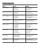
troubleshooting Problem Cause Remedy No power indication – Disconnect off. – Blown fuse. – Master button in. – Turn disconnect on. – Check / replace fuse. – Pull button out. No display on operators console – Program fault. – Faulty wiring. – Check lights on P.C. – Check plug on console. Power on – no motion – Program fault. – Drive fault. – Program error. – Check lights on drive. – Check lights on servo drive readout. – Check parameters.
troubleshooting (continued) Problem Cause Remedy Material feeds off center – Edge guides not set properly. – Material not centered to feed. – Bad material. – Set edge guides. – Center material. – Try new roll of material. No automatic cycle – No Press signal. – Check Press. SW. input to servo control. – Check lights on drive. – Check parameters on display. – Controller fault. – Servo fault. – Program error. Servo squeals – Servo velocity gain too high. – Belt too loose or tight.
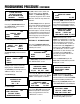
Programming procedure Operator Interface Terminal This section is to familiarize an operator with the terminal screen (program) flow. Also, the section will explain how to move from screen to screen. The screen flow is divided into five parts as set up in the home screen – “MAIN MENU”. These divisions are: 1. 2. 3. 4. 5. 6. 6.
Programming procedure (continued) A VALID JOB # MUST BE ACTIVE TO GO ON GO TO JOB ENTER SCRN JOB SCRN F6=EXIT SECTION 2 F2 - MANUAL MODE Pressing F2, manual mode while on the “MAIN MENU”, will cause the following the screen. EXIT MANUAL MODE INCH FEED SGL MODE LENGTH F1, inch mode, produces the following: EXIT SELECT JOG MODE CONTINUOUS INCH 1 JOG LENGTH F3, feed sgl length, produces the following: EXIT JOB 00 LENGTH = 00.
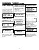
Programming procedure (continued) SECTION 4 F4 - JOB VALUES REVIEW F4, job values, on the “MAIN MENU” screen displays the following screen until F6, exit, is pushed. This screen lists the current active job number, the feed length, the SPM, the percentage of speed, the percentage of acceleration, and if a pilot is used. JOB # 00 VALUES = FEED LENGTH = 00.
troubleshooting A normally running drive will display an 8 in the LED box, top center. The LED box will display error and fault codes. The keypad can display additional error codes and information about system operational problems. LED Box Error Codes Display Description 0. Internal communications error 1. DC Bus overvoltage level – possibly too high of deceleration 2. Internal overcurrent, short circuit, over temperature or under voltage fault 3. Drive overcurrent – check motor cable 4.
troubleshooting (continued) Can Status LEDs There are two CAN LEDs , the left LED shows activity on the CAN1 (CANopen) bus. The right LED shows activity on the CAN2 (Baldor CAN) bus. Each LED can appear green or red. The states have the following meanings: = Not lit: No power to the card. = Green: The bus is operational; it is experiencing little or no errors. = Red, flashing: The bus is passive; it is experiencing some errors. = Red: The bus is off; it has experienced a fatal number of errors.
led status symbols Symbol Description Drive / comms watchdog. Internal communications failure. Clear the error; if the problem persists then contact Baldor technical support. Over volts. The DC Bus voltage has exceeded the overvoltage level. Check the AC supply voltage is correct for the unit. Check the DC Bus level. This should be close to the nominal voltage. If the input voltage is correct, then this error may be the result of high deceleration rates.
led status symbols (continued) Symbol Description Power base not ready. This error condition applies only to 3-phase models. These drives have a pre-charge circuit which must activate after power-up before the drive can be enabled. If the drive is enabled before this then the error occurs. The error could also indicate the loss of one or more of the input phases. Cam. A cam profile is in progress. General error.
led status symbols (continued) Symbol Description Preset trapezoidal move active (in motion). DB Overload. The regeneration resistor (Dynamic Brake) has been overloaded. Stop. A STOP command has been issued or the stop input is active. Drive disabled. The drive must be enabled before operation can continue. A number of actions are required to enable the drive. See the installation manual supplied with your product. Crash (various).
16 SMS - Feed
17 SMS - Servo Feed
18 SMS Control Panel Assembly
19 SMS Wiring Schematic
warranty Warranty Terms & Conditions All sales by the company are made subject to the following terms and conditions. please read. WARRANTY – The Company warrants, for a period of one year from date of shipment by the Company, that the product shipped is free from defects in material and workmanship. THIS WARRANTY IS EXCLUSIVE AND IN LIEU OF ALL IMPLIED WARRANTIES IN LAW, INCLUDING MERCHANT - ABILITY. The Company obligation under this warranty is limited to repairing or replacing, F.O.B.