Straightener operating instructions Models sc series (adjustable platen stock straightener – includes sa3 through sch18) Rapid-air corporation 4601 Kishwaukee St. • Rockford, IL 61109-2925 Phone: (815) 397-2578 • Fax: (815) 398-3887 • Web Site: www.rapidair.
table of contents Straightener Layout Sheet......................................................................................................................... pg. 3 Straightener Specification Sheet............................................................................................................. pg. 4 Installation.................................................................................................................................................... pg. 5 Start-Up Procedure........
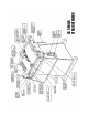
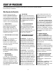
sc series straighteners
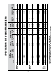
high speed speed .007-.025 .015-.070 .015-.050 .015-.036 .015-.075 .015-.050 .015-.036 6 6 12 18 6 12 18 500 lb. 1500 lb. 1500 lb. 1500 lb. 1500 lb. 1500 lb. 1500 lb.
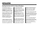
installation Operating Instructions for SC Series Powered Straightener The straightener that you just received is fully assembled and tested and ready to be put into position. CAUTION: Due to shipment vibration, it should be checked to be sure that all screws and bolts are secure and all electrical components are in place inside the cabinet, visually inspect the complete machine for physical damage due to shipment and handling.
Start up procedure Prior to applying power to the straightener, all the controls on the machine should be reviewed. A brief summary is listed below. Main Console And Controller The main control console with controls is mounted on the cabinet of the straightener. Located on the face of the console are five switches, one potentiometer, one push-button and one or two circuit breaker reset switches, which are explained below. 4.
dancer arm loop Dancer Arm Loop Height Adjustment Three different loop sensing arm operating positions are selected manually during set-up. By selecting the higher number, the zero point of the dancer arm is raised from its rest position to the angle shown (as indicated 0-2). The dancer arm will move from rest position to the angle selected before the straightener rolls begin to rotate.
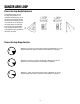
standard straightener components Curve Up/Down Adjustment Entrance Guide Roll Block Some applications have dies that cannot accept anything but flat stock and other dies run better with the material curving up or down to miss the built in edge required in the die. Before this feature was added, operators would under straighten or over straighten the material to suit their needs but in doing so would severely change the material entering the die.
operation Once the straightener has been tested and all the functions work then it should be tested for what it was designed to do and that is to remove coil set. Retract all of the idler rolls and the exit pinch roll to a position so when the cover is closed the material is not being deformed. Open the cover of the straightener and position the edge guides for maximum width.
troubleshooting guide MAIN SWITCH ON BUT NOT LIT 1. CB tripped. a. Reset CB. 2. Unit not plugged into main power. a. Plug into main power source. 3. No power in incoming line. a. Check outlet. b. Check power cord. 4. Loose wiring. a. Check terminals and connections. MOTOR CREEPS IN STOP POSITION 1. R1 & R3 pot on 69100034 board not correctly adjusted. a. Readjust pots so rollers stop. Call factory. UNIT TURNS BUT WON’T JOG 1. Selector switch not in jog position. a. Select jog. 2.
69100034 TAUT STOCK OUTPUT The 69100034—Proportional control board has a taut stock output. The output must be wired to a solid state relay as the max current draw is 20 MA. The solid state relay’s contact can then be incorporated into the electrical control circuitry. The output can be wired so that the relay is either on or off with the dancer arm down. When the dancer arm reaches the set point for taut stock, the relay switches state.
safety warning – please read carefully RAMM Solid State DC Motor Speed Control This product should be installed and serviced by a qualified technician, electrician or electrical maintenance personnel familiar with its operation and the hazards involved.
INTRODUCTION RAMM Full Wave Solid State DC Motor Speed Control The RAMM Full Wave Solid State DC Motor Speed Control represents the latest state-of-the-art design achievable through modern technology. 3. Follow the recommended supply wire sizes as per table 3. 4. Follow the NEC and other electrical codes that apply. CAUTION: SEPARATE BRANCH PROTECTION MUST BE PROVIDED ON 240V CIRCUITS. 5. Connect control in accordance to connection diagram.
INTRODUCTION (cont.) CAUTION: 1. The voltage feeding P2 and F– must be isolated from the AC line. Do not ground P2 or F– to set up a zero ground reference. 2. Do not bundle signal wires to P2 and F– with AC line motor connections. If signal wires are over 18”, use shielded cables. C. FUSING The RAMM has provision for a built in AC line fuse and armature fuse. The AC line fuse protects the control against catastrophic failure.
adjustments and control functions RAMM Adjustments And Control Functions WARNING: If adjustments are made under power, insulated adjustment tools must be used and eye protection must be worn. The RAMM has been factory adjusted to provide 0-full speed using the speed control knob. Minimum and Maximum speed trimpots are provided to change the speed from other than 0-full speed.
warranty Limited Warranty – RAMM 125, 225, 225D For a period of one (1) year from date of original purchase Rapid-Air Corporation will repair or replace without charge devices which our examination proves to be defective in material or workmanship. This warranty is valid if the unit has not been tampered with by unauthorized persons, misused, abused or improperly installed and has been used in accordance with the instructions and/or ratings supplied.
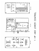
19 Wiring Diagram for STD Speed Straighteners (1-HP)
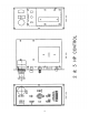
20 Wiring Diagram for High Speed Straighteners (3-HP)
21 Wiring Diagram for Medium Speed Straighteners (2-HP)
22 Parts List
23
24
25 Typical Stamping Layout