DATASHEET Raspberry Pi Compute Module 3+ Raspberry Pi Compute Module 3+ Lite Release 1, January 2019 Copyright 2019 Raspberry Pi (Trading) Ltd. All rights reserved.
Compute Module 3+ Datasheet Copyright Raspberry Pi (Trading) Ltd. 2019 Table 1: Release History Release Date Description 1 28/01/2019 First release The latest release of this document can be found at https://www.raspberrypi.
Compute Module 3+ Datasheet Copyright Raspberry Pi (Trading) Ltd. 2019 Contents 1 Introduction 5 2 Features 2.1 Hardware . . . . . . . . . . . . . . . . . . . . . . . . . . . . . . . . . . . . . . . . . . 2.2 Peripherals . . . . . . . . . . . . . . . . . . . . . . . . . . . . . . . . . . . . . . . . . 2.3 Software . . . . . . . . . . . . . . . . . . . . . . . . . . . . . . . . . . . . . . . . . . .
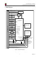
Compute Module 3+ Datasheet Copyright Raspberry Pi (Trading) Ltd. 2019 List of Figures 1 2 3 CM3+ Block Diagram . . . . . . . . . . . . . . . . . . . . . . . . . . . . . . . . . . . 7 CM3+ Mechanical Dimensions . . . . . . . . . . . . . . . . . . . . . . . . . . . . . . . 8 Digital IO Characteristics . . . . . . . . . . . . . . . . . . . . . . . . . . . . . . . . . .
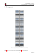
Compute Module 3+ Datasheet Copyright Raspberry Pi (Trading) Ltd. 2019 List of Tables 1 2 3 4 5 6 7 8 9 10 Release History . . . . . . . . . . . . . . . . . . Compute Module 3+ SODIMM Connector Pinout Pin Functions . . . . . . . . . . . . . . . . . . . Absolute Maximum Ratings . . . . . . . . . . . DC Characteristics . . . . . . . . . . . . . . . . Digital I/O Pin AC Characteristics . . . . . . . . Power Supply Operating Ranges . . . . . . . . . Mimimum Power Supply Requirements . . . . .
Compute Module 3+ Datasheet Copyright Raspberry Pi (Trading) Ltd. 2019 1 Introduction The Raspberry Pi Compute Module 3+ (CM3+) is a range of DDR2-SODIMM-mechanically-compatible System on Modules (SoMs) containing processor, memory, eMMC Flash (on non-Lite variants) and supporting power circuitry. These modules allow a designer to leverage the Raspberry Pi hardware and software stack in their own custom systems and form factors.
Compute Module 3+ Datasheet Copyright Raspberry Pi (Trading) Ltd. 2019 2 2.1 Features Hardware • Low cost • Low power • High availability • High reliability – Tested over millions of Raspberry Pis Produced to date – Module IO pins have 15 micro-inch hard gold plating over 2.5 micron Nickel 2.2 Peripherals • 48x GPIO • 2x I2C • 2x SPI • 2x UART • 2x SD/SDIO • 1x HDMI 1.
Compute Module 3+ Datasheet Copyright Raspberry Pi (Trading) Ltd.
Compute Module 3+ Datasheet Copyright Raspberry Pi (Trading) Ltd. 2019 4 Mechanical Specification The CM3+ modules conform to JEDEC MO-224 mechanical specification for 200 pin DDR2 (1.8V) SODIMM modules and therefore should work with the many DDR2 SODIMM sockets available on the market. (Please note that the pinout of the Compute Module is not the same as a DDR2 SODIMM module; they are not electrically compatible.
Compute Module 3+ Datasheet Copyright Raspberry Pi (Trading) Ltd.
Compute Module 3+ Datasheet Copyright Raspberry Pi (Trading) Ltd.
Compute Module 3+ Datasheet Copyright Raspberry Pi (Trading) Ltd. 2019 6 Electrical Specification Caution! Stresses above those listed in Table 4 may cause permanent damage to the device. This is a stress rating only; functional operation of the device under these or any other conditions above those listed in the operational sections of this specification is not implied. Exposure to absolute maximum rating conditions for extended periods may affect device reliability.
Compute Module 3+ Datasheet Copyright Raspberry Pi (Trading) Ltd. 2019 Symbol Parameter voltagea Conditions Minimum Typical Maximum Unit VDD IO = 1.8V VDD IO = 2.7V VDD IO = 3.3V - - 0.6 0.8 0.9 V V V VIL Input low VIH Input high voltagea VDD IO = 1.8V VDD IO = 2.7V VDD IO = 3.3V 1.0 1.3 1.6 - - V V V IIL Input leakage current TA = +85◦ C - - 5 µA CIN Input capacitance - - 5 - pF VOL Output low voltageb VDD IO = 1.8V, IOL = -2mA VDD IO = 2.7V, IOL = -2mA VDD IO = 3.
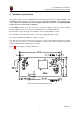
Compute Module 3+ Datasheet Copyright Raspberry Pi (Trading) Ltd. 2019 tfall trise DIGITAL OUTPUT Figure 3: Digital IO Characteristics 7 Power Supplies The Compute Module 3+ has six separate supplies that must be present and powered at all times; you cannot leave any of them unpowered, even if a specific interface or GPIO bank is unused. The six supplies are as follows: 1. VBAT is used to power the BCM2837 processor core. It feeds the SMPS that generates the chip core voltage. 2.
Compute Module 3+ Datasheet Copyright Raspberry Pi (Trading) Ltd. 2019 7.1 Supply Sequencing Supplies should be staggered so that the highest voltage comes up first, then the remaining voltages in descending order. This is to avoid forward biasing internal (on-chip) diodes between supplies, and causing latch-up. Alternatively supplies can be synchronised to come up at exactly the same time as long as at no point a lower voltage supply rail voltage exceeds a higher voltage supply rail voltage. 7.
Compute Module 3+ Datasheet Copyright Raspberry Pi (Trading) Ltd. 2019 When initially powered on, or after the RUN pin has been held low and then released, the BCM2837 will try to access the primary SD/eMMC interface. It will then look for a file called bootcode.bin on the primary partition (which must be FAT) to start booting the system.
Compute Module 3+ Datasheet Copyright Raspberry Pi (Trading) Ltd. 2019 All GPIOs except GPIO28, 29, 44 and 45 have weak in-pad pull-ups or pull-downs enabled when the device is powered on. It is recommended to add off-chip pulls to GPIO28, 29, 44 and 45 to make sure they never float during power on and initial boot. 9.1.
Compute Module 3+ Datasheet Copyright Raspberry Pi (Trading) Ltd.
Compute Module 3+ Datasheet Copyright Raspberry Pi (Trading) Ltd. 2019 9.1.4 SD/SDIO Interface The BCM283x supports two SD card interfaces, SD0 and SD1. The first (SD0) is a proprietary Broadcom controller that does not support SDIO and is the primary interface used to boot and talk to the eMMC or SDX x signals.
Compute Module 3+ Datasheet Copyright Raspberry Pi (Trading) Ltd. 2019 9.6 Composite (TV Out) The TVDAC pin can be used to output composite video (PAL or NTSC). Please route this signal away from noise sources and use a 75 ohm PCB trace. Note that the TV DAC is powered from the VDAC supply which must be a clean supply of 2.5-2.8V. It is recommended users generate this supply from 3V3 using a low noise LDO.