
User`s manual

Rastergraf
General Information 1-11
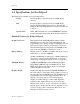
Fuse Element: The +5V supplied to the front panel connectors is protected
by a Positive Temperature Coefficient (PTC) resistor. It
resets automatically when the overload is removed.
Local I
2
C Channel: The Eclipse3 uses I
2
C, a 2 wire serial bus, to control the
following on-board devices:
THC63DV164 DVI transmitter (optional)
LM75 thermal sensor (optional)
AT24C02 2 Kb serial EEPROM (optional)
DDC2B display monitor control
Power-management: With the proper software, the Borealis can power-down
unused functions and the VESA standard DDC2B lines
control the monitor.
PCI Bus Access: Programmable Bus Address Registers (BARs) in the
Borealis map control and drawing engine registers, and
display memory through its 33/66 MHz PCI interface.
PCI bus Interrupts: The Borealis can interrupt the PCI bus on the INTA line.
Bus Loading: One PCI 2.1 compatible load
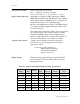
Module Size: PMC: IEEE 1386-2001,
149 mm x 74 mm, 32-bit, 33/66 MHz, J1/J2
CompactPCI: PICMG 2.0 Rev 3, IEEE 1101.10,
3U form factor w/ ESD strip,
32-bit, 33/66 MHz, J1 only, no hotswap.
3U and 6U front panel options.
Optional rear-panel module connecting to
CPCI J2 is standard 3U rear I/O format.
3U and 6U rear panel options.
PCI: short PCI, 32-bit, 33/66 MHz, 64-bit
connector set is used for improved power
and ground distribution
PCI Subsystem Vendor ID: 0x10F0 (CW Vendor Code)
PCI Subsystem Device ID: 0x0003 for 16 MB boards, 0x0007 for 32 MB boards
Power Requirements: Standard versions REQUIRE that the PMC, CompactPCI,
or PCI bus connectors supply both +5V and +3.3V. A
location for a local 3.3V regulator is provided on the PMC
and PCI boards for systems which do not supply 3.3V to
the backplane.
+5V +/- 5%, 0.2 A max
+3.3V +/- 5%, 1.2 A max
PCI Bus pin PRSNT1# is set low, indicating 7.5W max.