
User`s manual

Rastergraf
1-14 General Information
1.5 Eclipse3 Connectors and Cables
There are two possible connector locations on the front panel of the
Eclipse3 graphics boards.
Note:
Due to front panel space limitations, the PMC board can have either the
VGA or the DVI connector installed. The PCI and CompactPCI boards
have both installed.
The Eclipse3 “Standard” versions use a standard 15-pin VGA compatible
connector. RGBHV (Red, Green, Blue, and Horizontal and Vertical sync)
and DDC/DDA monitor control signals are supplied.
The Eclipse3 DVI option use a DVI-I 29-pin connector. This connector
supplies: RGBHV (Red, Green, Blue, and Horizontal and Vertical sync),
DDC/DDA monitor control signals, as well as DVI digital video output.
An adapter connector (Molex 88741-8700, available from Digikey) is
available from Rastergraf that adapts the DVI-I to a standard VGA
connector.
The CPCI rear-panel I/O option includes a rear I/O module with VGA
and/or DVI connectors mounted to either a 3U or 6U panel.
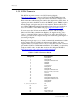
The following sections detail the applicable pinout information.
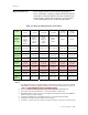
Connector Description Section
15-pin D-Sub
VGA
1.5.1
29-pin DVI-I DVI-I Connector 1.5.2
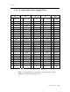
2 x 64 PMC PMC Connections (J1 and J2) 1.5.3
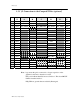
1 x 96 PCI PCI Connections (32/64) 1.5.4
1 x 125 2 mm CompactPCI Connection (J1) 1.5.5
1 x 110 2 mm Optional CompactPCI Connection (J2) 1.5.6