
User`s manual


Rastergraf
2-4 Installing Your Peritek Graphics Board
2.3.3 Changing the Jumpers
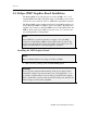
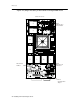
In the following subsections, please refer Figure 2-1 in Section 2.4 for
PMC, Figure 2-5 in Section 2.5 for PCI, and Figure 2-7 in Section 2.6 for
CompactPCI for to the parts layouts and jumper locations.
JP201: VGA PCI Device Jumper
JP201 selects the board to respond either as a PCI sub-class “VGA
Controller Device” (default) or as an “Other Display Controller” (jumper
installed). You may need to install this jumper on the second board when
you have two Eclipse3 boards installed in a PC compatible machine to
prevent the system BIOS from loading the Eclipse3 BIOS code twice.
JP101: Sync-On-Green Select Jumper
The Eclipse3 has the Rastergraf Quad Image BIOS (QIB) PROM, which
supports FCode, VGA, DVI, and Sync-On-Green (SOG). The firmware
can “determine” the need to run FCode or VGA and if the DVI monitor is
plugged in, it will select DVI mode without user intervention. However, a
separate jumper is needed to “tell” the firmware that SOG is required.
Normally, if SOG is requested prior to order shipment, JP101 is installed
at the factory. But, if it has been omitted, then install JP101 to enable
SOG.
JP202 (PMC): Reserved Jumper
JP202 is a factory use only jumper. Please do not attempt to use it.
JP233 (PCI): Local 3.3V Regulator Enable
If the graphics board was built with the optional local 3.3V regulator,
install JP233 to enable the regulator to supply power to the graphics board
when the PCI backplane only has 5V.
JP102 (CompactPCI) Frame Ground to Chassis Ground Jumpers
Ordinarily, frame ground and chassis ground are isolated from each other.
Install JP102 to connect them together.
Note:
Make sure before installing the jumper that this does not expose the
system to any electrical hazards.