
User`s manual

Rastergraf
Installing Your Peritek Graphics Board 2-13
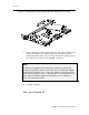
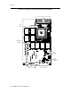
2.6 Eclipse3CPCI Board Installation
The Eclipse3CPCI board can plug into any 32-bit, 5V or 3.3V signaling
CompactPCI 3U or 6U slot. Although the board is usually supplied with a
6U faceplate, a 3U faceplate is also available. The board uses only the J1
connector unless the Rear I/O option is included.
Installing the Graphics Board
Note:
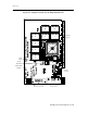
Refer to Section 2.3.3 for the settings for JP101, JP102, and JP201.
1. Shut down the operating system and turn off the power.
Warning!
Never open the computer without turning off the power supply. Unless
internal AC wiring is exposed, leave the power cord plugged in, so as to
ground the computer chassis. You can easily get shocked, ruin computer
parts or both unless you turn off the power. Even with power switched off,
lethal voltages can exist in the equipment.
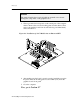
2. Open the computer and identify the empty slot in the card cage that is
closest to the CPU. Do not leave any slots empty between the graphics
board and the CPU.
The Eclipse3CPCI board is a Universal PCI device and can be plugged
into a slot which uses either 5V or 3.3V signaling protocol. Therefore,
a J1 connector signaling key plug is not necessary.
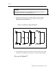
3. In the interest of allowing air flow, and if you have a choice, block off
any unused slots in the cardcage so that fan air will not flow through
them.