
User`s manual

Rastergraf
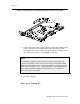
2-16 Installing Your Peritek Graphics Board
2.7 Finishing the Installation
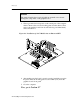
2.7.1 Connecting to the Monitor
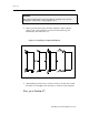
If you have an Eclipse3 Standard version board, plug a VGA cable into the
VGA compatible front panel connector.
If you have an DVI option board, use either a Rastergraf supplied breakout
cable or your own cable solution and plug into the DVI-I connector on the
graphics board’s front panel. You can use either a VGA (analog) or digital
(DVI) compatible monitor.
In either case, be sure to snug the connector’s thumbscrews down, as it
may otherwise work loose and cause unreliable operation. Make sure that
the 75 ohm switch on the monitor, if there is one, is turned on.
2.7.2 Checking your Display
Note
The Eclipse3 boards can supply 3 Wire (RGB with sync on green, BNC
connectors) or 5 Wire Video (RGBHV, VGA connector). Rastergraf
software defaults to 5 Wire Video (NO sync on green).
Be aware that if you connect a board that has video parameters set up for
sync on green to a VGA compatible monitor you will get a green
background on the display.
Another minor detail:
The Eclipse3 board may, depending on its original configuration as
supplied by Rastergraf, have its BIOS PROM programmed with VGA
BIOS, Sun SPARC compatible FCode, or, most commonly, both.
In the two former cases, obviously you can only use the board in a PC or
SPARC, respectively. In the latter case, you should be able to use the
board in either a PC or SPARC, and the system BIOS or OpenBoot should
figure out what to do.
Now, turn on the power and check your monitor’s display and proceed.