
User`s manual


Rastergraf
Programming On-board Devices 3-19
3.8 Talk To Me Through I
2
C
The Borealis chip has a control register that is used to implement the I
2
C
protocol, a 2 wire serial bus designed Philips Semiconductor. The Borealis
is the I
2
C master and it controls the bus through the DDC control register
in the Borealis chip. The I
2
C bus supports specific “start”, “stop” and
“acknowledge” states, so it is possible to probe for these devices and
determine whether they exist.
I
2
C is used to control the following devices:
Micrel MIC74 8-bit I/O register (optional)
THC63DV164 DVI digital video encoder/transmitter (optional)
LM75 thermal sensor (optional)
AT24C02 2 Kbit serial EEPROM
the Display Monitor
An I
2
C device is determined by a combination of device internal bits (bits
4-7) and (usually) three pins that are wired by the board designer (bits 1-3)
Bit 0 is used to denote a Read (1) or Write (0) operation.
Because the Eclipse3 board serial EEPROM and the Display Monitor have
a common I
2
C address (and this is not allowed) there is a 2 way
multiplexer on the Borealis board (see Section 3.5) that selects between
on-board I
2
C devices and the Display Monitor.
The LM75 must be read in 2 byte increments, otherwise it will hang the
I
2
C bus. Since most vendors combine the R/W bit with the actual I
2
C
address (e.g. write @ 0x88, read @ 0x89), the following table uses that
convention.
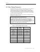
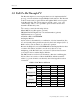
Table 3-5 I
2
C Device Addresses
Device R/W Binary Hex I2CMUX
W 0100 0000 0x40 x
MIC74
R 0100 0001 0x41 x
W 0111 0000 0x70 1
THC63DV164
R 0111 0001 0x71 1
W 1001 1100 0x9C 1
LM75
R 1001 1101 0x9D 1
W 1010 1000 0xA8 1
AT24C02
R 1010 1001 0xA9 1
W 1010 1000 0xA8 0
Display Monitor
R 1010 1001 0xA9 0