
Operation Manual


Pag.20
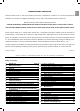
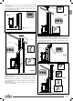
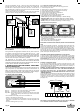
This type of installation (see fig. 7) does not require an insulated flue for
the part inside the house, whilst for the part outside, an insulated tube
must be used. In the lower part of the flue in the house, a union tee has
been installed with a peephole, but another one has also been installed
outside, so that the part can be inspected.
Two 90° bends should not be installed as the ash could quickly block the
passage of smoke, causing problems for the draught of the stove.
Operating faults due to flue draught problems or critical wea-
ther conditions
Among all weather and geographical conditions that may have an impact on
the operation of the draught fl ue (snow, rain, altitude above sl, fog, …) wind
is certainly the most important. In fact, in addition to the thermal depression
caused by the temperature difference between the inside and the outside of the
fl ue, there is another type of depression: dynamic depression caused by wind.
Therefore, wind has an impact on the effi ciency of the fl ue.
THE OPERATION OF THE PELLETS STOVE IS THEREFORE STRONGLY
DEPENDENT ON THE POSITION AND CONSTRUCTION OF THE FLUE. PRECARIOUS
CONDITIONS CAN ONLY BE RESOLVED WITH AN APPROPRIATE SETTING OF THE
STOVE BY RAVELLI APPROVED TECHNICAL PERSONNEL.
7. DESCRIPTION OF THE FUNCTIONING AND SYMBO-
LOGY OF THE DISPLAY
The innovation of this particular display is the communication through low volt-
age conveyed waves (12 volts) between the electronic motherboard and the
display. The communication is made trough a bipolar cable (ex: the cable for
the stereo speakers) and the novelty is the possibility to install the display in
the wall using the optional standard frame for electrical box 503.
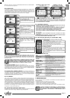
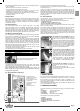
7.1. Display with mode “BASE”
Calender
Room temperature
Clock
Working power
Stove status
Key “1”:
access key to “set room temperature” and regulation
Key “2”:
access key to “set power” and regulation
Key “OK”:
short press of the key to confirm and come back to the main
screen; press the key 3 seconds long to switch on and switch
off the stove.
The functionalities of this display when used in mode “BASE” are:
•
Switch on and switch off of the stove
•
Set of the room temperature and selection of the type of sensor (sup-
plied sensor connected to the motherboard or sensor integrated to the
display)
•
Set of the working power (1,2,3,4,5)
7.1.1. switch on and switch off of the stove
Before starting the stove please follow following procedure :
1.
Connect the power cable
2.
Set the switch on the backside of the stove on position 1
3.
Check that the installation is connected to the chimney
4.
Load the pellet tank with 6 mm pellets
5.
Load the screw as described in paragraph 8.6
6.
Press key OK for 3 seconds long.
At this stage the stove will begin the ignition phase.
On the display will appear following writings:
•
START
(waiting time is different depending on default settings)
•
WAITING FLAME
(waiting time is different depending on default settings)
•
FLAME LIGHT
(waiting time is different depending on default settings)
•
WORK
(waiting time is different depending on default settings)
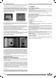
7.1.2. Set of the room temperature
Fig. 1 Fig. 2
The functioning of the stove with room thermostat activated is of 3 types:
•
With supplied room sensor positioned on the backside of the stove ( not
available for insert models)
•
With room sensor integrated to the display
•
With external thermostat (not supplied)
MODE WITH SUPPLIED ROOM SENSOR (DEFAULT AND SUGGESTED
USE)
If you use the supplied room sensor , the display will show the room tem-
perature. To set and modify the room temperature press key number 1 to
enter in the dedicated menu and set the desired value with key 1 and 2.
Confirm with key OK 2 times and keep deselected the box SENSOR CON-
SOLLE (flag, see pic.2). Once reached the set temperature the display
will show MODULATION WORK, so the stove will reduce to minimum the
pellet consumption and the power as well.
MODE WITH ROOM SENSOR INTEGRATED TO THE DISPLAY
in case you want to install the display on the wall instead of on the stove
as from the factory, please reference to the functioning with supplied room
sensor (as above explicated) with just one difference: the box (flag)
SEN-
SOR CONSOLLE
, if you work in this mode, should be selected by using
key 2. Then confirm with the key OK ( reference to pic. 1 paragraph 7.1.2.)
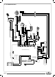
EXTERNAL THERMOSTAT MODE
if you use an external thermostat correctly connected as shown in the
electrical scheme ( reference paragraph 10), the display will not show the
room temperature but the writing T ON ( when the contact is closed) or T
OFF ( when the contact is open).
REMARK: TO ENABLE THE EXTERNAL THERMOSTAT ENTER IN THE
SET TEMPERATURE USING KEY 1 AND THEN PRESS REPEATEDLY
TO REACH THE VALUE “EST” ON THE DISPLAY; CONFIRM TWO
TIMES WITH THE KEY OK KEEPING DESELECTED THE BOX (FLAG)
“
SENSOR CONSOLLE”.
Once reached the set temperature of the thermostat the display will show
MODULATION WORK, so the stove will reduce to minimum the pellet
consumption and the power as well. If activated the mode COMFORT
CLIMA, the stove will switch on and off automatically (for details reference
paragraph 8.2.)
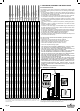
1 2 3 5 6 7 8 9 104
-TC1+TERM.N.AMB.
SMOKE
PROBE
ROOM
TERMOSTAT
ROOM
PROBE
-TC1+TERM.N.AMB.N.H2ON.PEL.
Red
Blue
Black
Black
WE ADVISE A ROOM TERMOSTATE WITH OFF-SET WITH OF MINIMUM
3°C IF WE WANT ACTIVATE CONFORT CLIMA,PROPERLY.
Insulated fl ue
Union tee for conden-
sation of insulation
H > 4 mt
H > 1,5 mt
2-3 metres
Max
3-5% gradient
Union tee for condensation