Instruction Manual for 98cm Elliptical Ku Antenna
Caution This instruction leaflet will assist you in the correct installation of the product. Read it prior to starting any installation work. Due to the nature of the method of manufacture, there may be sharp edges on metal components. Be cautious when un-packing and handling antenna parts. Warning Assembling dish antennas on windy days can be dangerous. The antenna surface, even in slight winds, creates strong forces. For example, a 1.
SITE SELECTION The first and most important consideration when choosing a prospective antenna site is whether or not the area can provide an acceptable “look angle” or Line-of-Sight (LOS) at the satellites. A site with a clear, unobstructed view of the southern sky is necessary. Also, consider obstruction that may occur in the future, such as the growth of trees. Using a Site Survey, select your antenna site in advance of the installation, so that you will be able to receive the strongest signal available.
Table of Contents KEY COMPONENTS................................................................................................................................................................................. III HARDWARE LIST........................................................................................................................................................................................ I ANTENNA ASSEMBLY .................................................................................
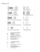
1 3 2 4 5 7 6 -iv-
Hardware List QTY 5 5 5 6 5 10 6 Antenna Assembly Hardware Description 5/16 UNC x 1" carriage bolt 5/16 UNC x 3/4" carriage bolt 5/16 UNC x 3/4” hex head tap bolt 5/16 UNC hex nut 5/16 UNC serrated flange nut 5/16 UNC washer 5/16 UNC spring washer QTY Feed Mounting Hardware Description 2 2 2 2 2 5/16 x ½” UNC hex head tap bolt 5/16 UNC Washer 5/16 UNC Spring Washer M4 x 10mm Hex Socket Head M4 Spring Washer -v-
Antenna Assembly Complete the antenna assembly on the ground, before mounting it on the Mount Tube. This assembly has three steps. Step 1: Construct the Skew Adjustment Assembly by fastening the Skew Plate to the front of the Elevation Bracket, through the Antenna Back Bracket. Locate the letter A on the skew plate and the letter A on the elevation bracket. Pass five 5/16” x 1" UNC Carriage Bolts through the skew plate, then the Antenna Back Bracket, and, finally, through the front of the Elevation Bracket.
Step 2: Boom Arm Assembly Installation; Slide the Boom arm assembly into the slots at the bottom of the Antenna Back Bracket, aligning the screw holes. To fasten the Boom arm to the Antenna Back Bracket, insert one 5/16” x 3/4 “ UNC Hex Head Tap Bolt and washer into each of the four screw holes in the slot and tighten with a ½” wrench to 20Nm (177 in lbf) (fig 2).
Step 3: Ku Feed Installation; Attach the Feed Horn to the cradle using a 5/16” x ¾” UNC Hex Head Tap Bolt, 5/16” flat washer, 5/16” spring washer and 5/16” hex nut and tighten with a ½” wrench to 20Nm (177 in lbf) (fig 3).
Step 4: Mounting the Antenna. Before attaching the Reflector to the Antenna Bracket, it is necessary to mount the system on to the Mount Tube. The mount location should be of a sturdy construction i.e. solid wall or wall studding. Use a Spirit Level to verify the horizontal and vertical level of the Mount Tube Taking heed of the safety instructions mentioned at the start of this instruction manual, carry the Antenna pre-assembly to the Mount Tube location.
Step 5: Fasten the Reflector to the Antenna Back Bracket by using one 5/16" x 3/4" UNC Carriage Bolts inserted through the top hole on the dish and place a 5/16" UNC Serrated Flange Nut on the bolt. Carefully holding the reflector, locate the bolt and lower the reflector onto the antenna bracket by sliding the bolt down through the fork if the top tab on the antenna bracket. Use the remaining 5/16” x ¾”UNC carriage bolts and through the four remaining tabs located on the Antenna Back Bracket.
Line of Sight (LOS) Adjustment The following section describes the processes to adjust the antenna to the correct Line of Sight (LOS). It includes both coarse and fine adjustment of the Azimuth and Elevation settings, along with the skew adjustment process if required. Figure 6 Skew Adjustment Slightly loosen the five 5/16” x 3/4" UNC Carriage Bolts fastening the Elevation Bracket to the Skew Plate through the Antenna Back Bracket.
Elevation Coarse Adjustment: Slightly loosen the 5/16” X 3/4" UNC Carriage Bolts in the arched slots at the bottom sides of the Elevation Bracket. Insert the handle as shown in (fig 7). Rotate the handle to adjust the elevation until the approximate value supplied with the Work Order matches the elevation setting. With the use of the inclinometer shelf, it is possible to coarsely elevate the antenna to the desired setting.
Azimuth Fine Adjustment: To fine adjust the Azimuth slacken the four 5/16” x 3/4" UNC Carriage Bolts in the bottom of the Azimuth Base. Next, turn the 2 1/2" x 5/16” UNC Hex Cap Bolt through the hole on the right side of the Azimuth Base to give you the azimuth angle you require. After verifying the Azimuth with a compass and a meter, lock down the four 5/16” x 3/4" Carriage Bolts in the bottom of the Azimuth Base to 20Nm (177 in.