M7-UC Tech n ic a l M an ua l Version A2 December 2015 Raveon Technologies Corporation 2320 Cousteau Court Vista, CA 92081 www.raveontech.
Table of Contents 1. General Information about the M7-UC ........................................................... 5 1.1 1.2 1.3 1.4 1.5 1.6 1.7 1.8 1.9 2 Overview ........................................................................................................ 9 2.1 3 Features ........................................................................................................................................ 9 Specifications.................................................................
Addressing Examples: ..........................................................................................................................33 6.6 Error Correction ............................................................................................................................34 6.7 Store-and-Forward Repeating and Routing ..................................................................................35 Using the M7-UC Modem – Streaming Mode .................................................
Symptom: Symptom: Symptom: Symptom: Symptom: 16 Receive light blinks, but no data is received .......................................................................66 Long delay before transmitting ...........................................................................................67 Modified parameters are lost at power-up ..........................................................................67 Cannot enter Command Mode .........................................................................
1. General Information about the M7-UC 1.1 Congratulations! Congratulations on your purchase of a M7-UC radio modem – the most advance UHF radio modem available today. Please take a few minutes to read this manual carefully. The information presented here will allow you to derive maximum performance from your radio modem. After reading it, keep the manual handy for quick reference, in case questions arise later on. 1.
FCC MPE Regulations: WARNING: It is the responsibility of the user to guarantee compliance with the FCC MPE regulations when operating this device in a way other than described in this manual. Human body Exposure: This equipment is approved only for mobile and base station transmitting devices, separation distances of (i) (ii) 1.
1.5 Antenna Compliance Information The radio modem must be used in fixed vehicle-mount configurations or at fixed base-station sites. It is not intended for portable applications. Antenna Installation: For rear deck trunk installation, the antenna must be located at least the following range away from rear seat passengers and bystanders in order to comply with the FCC RF exposure requirements. For vehicular roof top installation, the antenna must be placed in the center of the roof.
456.00 MHz – 460.00 MHz 460.0000 MHZ - 462.5375 MHz 462.7375 MHz - 467.5375 MHz 467.7375 MHz – 470.0000 MHz 1.9 Industry Canada Compliance Category I radio communication devices comply with Industry Canada Standard RSS-119. This device complies with Industry Canada licensed RSS standard(s). Conformité aux normes d’Industrie Canada Dispositifs de communication radio de catégorie I sont conformes à la norme Industrie Canada RSS – 119.
2 Overview The M7-UC data radio is a rugged high-performance, high-speed narrowband data modem. It contains a receiver, a transmitter, and modem, creating an easy-to-use transparent data radio link. The M7-UC’s user interface is asynchronous RS-232 data into and out of the M7-UC (CMOS level optional). Modem operation is virtually transparent to the user and the configuration of the modem is via the user serial port.
3 Specifications 3.1 General All measurements made per TIA-603-B Frequency: Model M7-UC ................................................................................................ 450 – 470MHz Size ..........................................................................................................3.0D X 3.76W X 1.40H Weight ................................................................................................................. 6 ounces (0.
3.3 Receiver Typical RX sensitivity (1% BER) 9600bps, 4-level, 12.5kHz channel ........................................................................ -109dBm 4800bps, 2-level ..................................................................................................... -115dBm 2400bps.................................................................................................................. -116dBm 1200 ........................................................................................
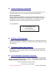
4 Electrical Inputs and Outputs The front panel of the M7-UC modem has these features: 1. RF connector 2. Power LED 3. Status LED (Receive data = green, TX = red) 4. 9-Pin Serial I/O connector 5. DC Power Jack 4.1 LEDs The status LED visually show the current status of the radio. Status LED (TX) This LED blinks red when the transmitter keys and is putting out RF power. It blinks green upon the reception of data or RF carrier.
RS232/EIA232 Serial I/O Connector The RS232 9-pin serial I/O connector is a female 9-pin D-subminiature connector having the following pins configuration. It is pinned out so that it may be plugged directly into a computer or PC’s 9-pin COM port.
4.3 EIA-485/RS-485 Serial I/O RS-485 Connector Pin Out With the RS-485 enabled (ATIO 2 command), the 9-pin serial I/O connector on the front of the M7-UC is a female 9-p D-subminiature connector having the following pins configuration. Front-view of DB-9 connector on modem (female) Pin # 1 2 3 4 5 6 7 8 Name Dir Function B (-) A (+) I/O I/O Do not connect Do not connect B A Ground Do not connect Do not connect this pin to anything. Do not connect this pin to anything.
Bias and Termination Resistors RS-485 installations typically have a termination resistor across the A and B lines. For low-speed operation (<57600 baud), this resistor is probably not necessary. If you wish to use a terminating resistor, a value of 150 ohms should work in most applications. These A/B pin names are all in use on various types of equipment. The RS485 signaling specification states that signal A is the inverting or '-' pin and signal B is the non-inverting or '+' pin.
7 8 Out + In - 9 Vin out in In/Out TX out + RX input - 3.3,0V. DC Power DC Power in or out if unit is powered using DC in jack. Configuring for RS-422 To configure the M7-UC modem for RS-422 operation, use the ATIO 4 command. You must order the RS-422 option for this to work, and only M7UC modems with Revision E or higher hardware will work in RS-422 mode. The M7-UC’s hardware is identical to the RS-485 version, with the exception of two internal loop-back resistors.
The M7-UC can switch between LPM and normal mode using the DTR line, and it switches much faster than using the DC power supply. The M7-UC takes about ½ of a second to power on when DC is applied, but can switch between normal and LPM in about 25milliseconds. The factory default value for the ATRP setting is 0. When ATRP is a zero, the M7-UC will not ever enter the LPM mode, and the DTR input signal is ignored. DTR negated means it is a negative voltage.
5 Serial Port Commands 5.1 Overview Only trained radio technicians are allowed to modify the settings in this product. The serial port the RF modem is used to send and receive data over the air, as well as to configure the RF modem. In normal operation, the user sends data into the TxD pin of the user port, and this data is transmitted over the air. Received data from another RF modem is output to the user via the RxD pin of the user port. This is the default operating condition of the RF modem.
5.3 Setting a Parameter To set a parameter in the M7-UC modem, enter the Command Mode as described above. Then enter the proper AT command, a space, the parameter, and then a carriage return. For Example, to set the address of the M7-UC modem to 1234, enter the following command: ATDT 1234 . Once a Parameter is changed, the modem will begin using the new parameter as soon as it exits the Command Mode and returns to its normal operation mode.
M7-UC modem to assist in this case. This CONFIG button may be pressed at any time, and forces the modem into a known operational state. The CONFIG button is located inside the modem. Remove the rear cover, exposing the two circuit boards. The button is in the center of the lower circuit board as shown below. The default settings that the modem will revert to when the CONFIG button is pressed are: 1. Serial port 9600 baud, 8 data bits 1 stop, no parity 2. ATCT setting set to 60000 (60 second time-out) 3.
To erase ALL parameters, including the radio type and radio calibration, issue the AT&F 123 command. There should not be any reason do this command, because it will require the radio to be re-calibrated per the factory alignment procedure. Command Mode Commands AT Command Description Command Parameters Factory Default AK Enable/Disable ARQ – When ARQ is enabled, this modem will automatically send an ACK packet back to a modem that sends it data. 0=off, 1=on.
FT FR FX Transmit Frequency – Program the transmit frequency for this channel. Enter in Hz or in MHz. The frequency will automatically be saved in non-volatile memory (flash) for this current channel number. Receive Frequency – Program the receive frequency for this channel. Enter in Hz or MHz. The frequency will automatically be saved in non-volatile memory (flash) for this current channel number. TX and RX Frequency – Program the receive and transmit frequency for this channel. Enter in Hz or MHz.
4 = 8000 4L 9 = 2000 2L R3 Serial Port time out – Number of mS of no activity before transmitting. R5 Preamble length – The number of bytes to send over-the-air in the pre-amble. Range: 1 - 5000 20 (mS) 4** R8 R9 RA RB RF RG RQ RS RT RV SL Frequency Offset. Used to set the radio on the center of the radio channel. Modulation Balance. Select RF CD output threshold – This value is the RSSI threshold where the carrier detect is asserted.
Save – Save all the parameters to EEPROM. This command must be used if changed parameters are to be stored in nonvolatile memory, and used next time the modem is powered up. Modem exits configuration mode after this command is executed. It saves all parameters except the frequency (The frequency is automatically saved when an ATFT, ATFR, or ATFX command is executed) SV Transmit Random Data – When issued, the modem will begin sending random data. Entering a will terminate the transmission.
5.9 Factory Default Settings For the UHF M7-UC, model RV-M7-UC, the main factory defaults are: Channel 1 ....................................................... 464.500 MHz Over-the-air baud rate: ...................................... 4800 baud, 2-level Serial port .......................................................... RS-232, 9600baud, N/8/1 Hardware flow control ....................................... Off RF Power Output .............................................. 100% Channel number selected ..
6 Using the M7-UC Modem – Packet Mode This section describes the operation of the when it is in the Packet Mode of operation. Packet Mode is the factory-default operating mode. It is the easiest and most reliable mode of operation for a modem. Note: The configuration of the M7-UC is done when the M7-UC is in the “Command Mode”. Refer to Section 2 on page 18 for details on all of the available commands and programmable features.
thus can operate with weaker signals and have longer communication range. Figure 1 (Packet Mode of Operation) For operation of the modem in the streaming data, non-packetized mode, see the section Streaming Mode on page 37. The Packet or Streaming operation is configured using the ATMT command, with Packet Mode being the factory default. 6.1 Setup 1. Connect a DC power source to the DC IN connection on the front of the modem. 2.
shipped ready-to-use. Out of the box, they will communicate on the default radio channel using the factory defaults. In general, the parameters you may want to modify will be: ATFX Frequency for this channel. Set to your frequency. ATMT 0 0 for normal Packetized operation. Default mode. ATAK 0 for no ARQ, 1 if this unit sends ACKs. Default is no ARQ. ATRB Set the number of retries if ARQ is used (x). 0 if no ARQ used. Factory default is no ARQ. ATBD Serial port baud rate ATMY The ID of this unit.
If the channel number is changed using the ATHP command, and power is later lost, the channel number will be retained in non-volatile memory as long as was saved using the ATSV (Save to non-volatile memory) command. Due to the nature of the synthesizer used in the M7-UC’s radio, the frequency programmed into the unit must be an even multiple of its internal reference frequency. For narrow-band radios (12.5kHz channels), the user’s frequency must be a multiple of either 6.25khz or 5.00kHz.
than 80% full. When it is asserted and it is “Clear to Send”, the buffers are less than 80% full. Packet Size The over-the-air packet size may be set with the ATTT xx command. Once the modem receives one full packet of data into via the serial port, it will automatically key the transmitter and send the data. Factory default is 80 bytes.
6.5 Addressing (Packetized Mode only) Addressing Basics One of the more powerful aspects of the M7-UC modem is its addressing scheme. Incorporating addressing in the modem allows multiple radio systems on the same frequency to co-exist, and not interfere with each other. Also, some user application cannot tolerate receiving data that was not intended for it, and by setting the addresses in the modems properly, the system can be configured to allow reception of only data intended for the recipient.
Setting A System-Wide Address If individual addressing is not needed in your system, there are two ways to ensure it is not used. One way is to set all modems in the system with the same Unit Address and destination address. From the factory, these are both set to 1234, and thus, all modems can communicate with all other modems, using the address 1234.
Unit Address is compared to the Effective Destination Address, and if the two are identical, the data will be received.
Receiving M7-UC Unit Address = 1234 Receiving M7-UC Address Mask = FFF0 Result: Data will be received. 1236 ANDed with FFF0 is 1230. 1234 ANDed with FFF0 is 1230. The results of the ANDing match, and thus the data will be received. Example 4 (able to receive from a group, xx34 where xx is any two digits) Sending Destination Address = 2234 Receiving M7-UC’s Unit Address = 1234 Receiving M7-UC’s Address Mask = 00FF Result: Data will be received. 2234 AND 00FF equals 0034.
compromise. If after 5 times, the data does not get through, then there probably is something seriously wrong with the channel or system. The retried-transmissions are randomly spaced at intervals between approximately 200mS and 400mS, increasing by 50mS for each attempted transmission. Once the modem has sent its data the number of times the user specified in the ATRB xx command, the data is discarded, and the modem will continue to operate as normal.
To solve this problem, some of the M7-UC modems are configured as repeaters. The still are able to send and receive data, but they also will repeat data out to the modems that are out of range of M7-UC A. H is configured to repeat all messages to/from E, D, and G. B is configured to repeat all messages to/from C, and D is configured to repeat all messages to/from G. The following table illustrates one possible way the M7-UCs could be programmed to accomplish this type of system.
The second command above sets the Repeat Source to 1000 and the Repeat Destination to 1000, both with a Mask of FFFF. The FFFF mask means all digits of the source and destination are used to determine if the transmission should be repeated. All packets from units with MYID 1000 (A)sent 1000 will be repeated by this unit. In other words, all transmissions from A will be repeated by B. To view the Repeater Table, use the ATX command, with no parameter.
Using the M7-UC Modem – Streaming Mode This section describes the operation of the Streaming Mode of operation. This mode is selected with the command ATMT 2. 6.8 Streaming Mode Operation In Streaming Mode, radio transmissions will begin whenever data enters the mode, and the transmission will continue as long as there is data to send. The transmitter will automatically key when data enters the modem, and there is no need to assert any control lines.
8 Serial Port Commands 8.1 Overview Only trained radio technicians are allowed to modify the settings in this product. The serial port the RF modem is used to send and receive data over the air, as well as to configure the RF modem. In normal operation, the user sends data into the TxD pin of the user port, and this data is transmitted over the air. Received data from another RF modem is output to the user via the RxD pin of the user port. This is the default operating condition of the RF modem.
8.3 Setting a Parameter To set a parameter in the M7-UC modem, enter the Command Mode as described above. Then enter the proper AT command, a space, the parameter, and then a carriage return. For Example, to set the address of the M7-UC modem to 1234, enter the following command: ATDT 1234 . Once a Parameter is changed, the modem will begin using the new parameter as soon as it exits the Command Mode and returns to its normal operation mode.
M7-UC modem to assist in this case. This CONFIG button may be pressed at any time, and forces the modem into a known operational state. The CONFIG button is located inside the modem. Remove the rear cover, exposing the two circuit boards. The button is in the center of the lower circuit board as shown below. The default settings that the modem will revert to when the CONFIG button is pressed are: 4. Serial port 9600 baud, 8 data bits 1 stop, no parity 5. ATCT setting set to 60000 (60 second time-out) 6.
To erase ALL parameters, including the radio type and radio calibration, issue the AT&F 123 command. There should not be any reason do this command, because it will require the radio to be re-calibrated per the factory alignment procedure. Command Mode Commands AT Command Description Command Parameters Factory Default AK Enable/Disable ARQ – When ARQ is enabled, this modem will automatically send an ACK packet back to a modem that sends it data. 0=off, 1=on.
FT FR FX Transmit Frequency – Program the transmit frequency for this channel. Enter in Hz or in MHz. The frequency will automatically be saved in non-volatile memory (flash) for this current channel number. Receive Frequency – Program the receive frequency for this channel. Enter in Hz or MHz. The frequency will automatically be saved in non-volatile memory (flash) for this current channel number. TX and RX Frequency – Program the receive and transmit frequency for this channel. Enter in Hz or MHz.
4 = 8000 4L 9 = 2000 2L R3 Serial Port time out – Number of mS of no activity before transmitting. R5 Preamble length – The number of bytes to send over-the-air in the pre-amble. Range: 1 - 5000 20 (mS) 4** R8 R9 RA RB RF RG RQ RS RT RV SL Frequency Offset. Used to set the radio on the center of the radio channel. Modulation Balance. Select RF CD output threshold – This value is the RSSI threshold where the carrier detect is asserted.
Save – Save all the parameters to EEPROM. This command must be used if changed parameters are to be stored in nonvolatile memory, and used next time the modem is powered up. Modem exits configuration mode after this command is executed. It saves all parameters except the frequency (The frequency is automatically saved when an ATFT, ATFR, or ATFX command is executed) SV Transmit Random Data – When issued, the modem will begin sending random data. Entering a will terminate the transmission.
8.9 Factory Default Settings For the UHF M7-UC, model RV-M7-UC, the main factory defaults are: Channel 1 ....................................................... 464.500 MHz Over-the-air baud rate: ...................................... 4800 baud, 2-level Serial port .......................................................... RS-232, 9600baud, N/8/1 Hardware flow control ....................................... Off RF Power Output .............................................. 100% Channel number selected ..
Using the M7-UC Modem – Packet Mode. 8.10 Baud Rate Selection In Streaming Mode, the user data may still enter the modem at any baud rate, as set with the ATBD x command. The M7-UC modem will buffer the data and send it out over the air in the same order as it enters the modem. When the buffer is empty and there is no more data coming into the modem, it will automatically de-key the radio and go back into the receive mode.
8.13 Serial Data Flow Control If large amounts of data will be sent with the M7-UC, and the serial port is operated at a faster data rate than the over-the-air rate, it may be possible to overflow the internal data buffer. To ensure the transmit buffer does not overflow, enable and use hardware flow control. Hardware flow control is enabled with the ATCH 1 command. Note that the M7-UC modem will always indicate the status of its internal buffer using the CTS signal on the DB-9 serial connector.
9 Installation 1. Secure the M7-UC modem using the four mounting holes on the side flanges of the unit. 2. Connect a DC power source to the DC IN connection on the front of the modem. Use the supplied cable, and connect the RED wire to +, and the black wire to – (ground). The black wire and the case of the M7-UC should be connected to earth ground. 3. Connect a good quality antenna, tuned to the operating frequency, to the RF connector on the front of the modem.
wideband/narrowband, antenna type and size, power/wattage, etc. You'll also get information on how to obtain the necessary application forms - either in hardcopy or electronic format - and how to proceed. The FCC website also offers a list of Frequency Coordinators. These are private organizations officially certified by the FCC to help you through the process, and who in most cases will handle the actual filing of your application.
10.1 Setting the Over-The-Air Data Rate The SkyLine has programmable over-the-air baud rates. The over-the-air rate is stored in register R2, and is programmed with the ATR2 x command, where x is a number corresponding to the rate. The are many possible baud rates, but not all rates may be used with all radio modem models. Consult the following table. Over-the-air rate Radio Bandwidth Number of Modulation Levels M7-UC Modem Models that support the rates 800bps (R2=0) 12.
M7-UC-W (wide-band version) For high-speed operation, set R2 to 5 (9600 baud). For best range (longest distance), set R2 to 1 (1200 baud) Other data rates of 0(800bps), 2(2400bps), 3(4800bps), 7(9600bps), and 6(19,200bps) will work, but have a less optimal bit-error-rate vs. receive sensitivity. 10.2 Debug Related Commands Bench Testing (Must be in command mode to test. Enter +++ at the keyboard to put unit into config/test mode.) ATTD x Various transmit test routines. 0 = Go back to normal mode.
11 M7-UC Diagnostic Provisions 11.1 Overview of Diagnostics Internal to the M7-UC radio modem, is a powerful 32-bit microprocessor. Along with handing all aspects of radio modulation and demodulation, the microprocessor also maintains an extensive array of diagnostic information. This section details the diagnostic information available, and describes how to us the information to optimize or troubleshoot a M7-UC radio network. 11.
ST10 Statistic Read – Returns numeric values, comma separated, of all statistics as described in the ST command.
11.
11.6 ATST3 Command The ATST3 command, will return the time and date the firmware in the M7-UC was compiled. 11.7 ATST4 Command The ATST4 command will return internal timers that tell how long the modem has been powered up and running. All of these timers restart a 0 upon power up.
PRX The number of packets this modem has received. PTX The number of packets this modem has transmitted. The ID code that the status information is sent to, is set with the ATMA xxxx command. Whenever a status transmission is sent, the “TO ID” of the transmission is the address set using the ATMA command. This allows the system to be configured in a way the normal modem communications take place between the modems, and the status information only is delivered to modems that need to receive it.
12 Tune-up and Alignment Do not key the transmitter for more than 30 seconds out of every 150 seconds if the RF power is set above 2 watts. Radio calibration and alignment is performed using the ATRx commands. The M7-UC modem has been factory calibrated, in should not require any recalibration when installed, or when changing frequency or channel. Unless the user is trained in radio test and calibration, the values stored in the R registers should not be modified.
3. Adjust the deviation register setting so that the frequency deviation is correct. The deviation is set with a digital adjustment. Use the ATR0 command to read or set the deviation level. 12.4 TX Modulation Balance (Note: This step is not performed on radios with Radio Type 5) 1. Set-up a service monitor to monitor the FM deviation of the transmitted signal on an oscilloscope. The frequency response of the demodulated FM signal must be greater than 10Hz to 5kHz without any de-emphasis. 2.
5. Generate an RF signal on-channel with a level of -110dBm. Verify the Power/BUSY LED stays on. If it does not, repeat step 4, adjusting in increments of 10.
13 SkyLine Compatibility 13.1 General The M7-UC RF modem has built-in compatibility with a radio modem made by Sonik Technologies, Vytek Wireless, and Cal Amp called the SkyLine. In most applications, Raveon’s M7-UC modem can communicate with SkyLine modems, provided the M7-UC is properly configured. There are two versions of the Skyline, a wide-band version running at 9600 bps over the air, and a narrowband version running at 5142bps over the air. 13.
14Appendix A. Serial Port Hardware 14.1 Serial Port Data and Handshaking Signals In computer terminology, the RF modem is considered a “Data Communications Equipment” device, or DCE. The user’s hardware that the modem is connected to is considered “Data Terminal Equipment”, or DTE. Following is a description of how data and control is communicated over the various serial port signals between the modem (DCE) and another device (DTE) that the modem’s I/O port is connected to.
user is send data into the modem at 9600 baud, the modem will negate the CTS signal once the M7-UC’s internal data buffers become full. CD On this line the modem indicates to the DTE that it has received a carrier from a remote device. It will assert this signal any time there is a carrier detected. The modem may be configured to assert this when an RF carrier is detected (any onchannel RF, voice or data), assert it only when another RF modem signal is detected, or always assert it.
14.2 Null modem without handshaking Sometimes, a “Null Modem” cable may be required to connect the M7-UC modem to another device. The specific connections are very dependent upon the type of hardware and handshaking used, but the following sections should help in configuring a null-modem cable. How to use the handshaking lines in a null modem configuration? The simplest way is to don't use them at all.
14.4 Null modem with full handshaking In this null modem cable, seven wires are present. The cable is shown in the following figure. Null modem with full handshaking (DB-9 Female shown. Same wiring for male-to-male cable) 14.5 Connector 1 Connector 2 Function 2 3 Rx Tx 3 2 Tx Rx 4 6 DTR DSR 5 5 Signal ground 6 4 DSR DTR 7 8 RTS CTS 8 7 CTS RTS Compatibility issues The null modem cable with full handshaking does not permit the older way of flow control to take place.
15Troubleshooting Symptom: Unit will not receive Solution #1. Verify that the modem is on the correct RF channel. If it is, the RX LED should blink every time another modem tries to transmit to it. If the RX LED does not blink when it should be receiving, it is on the wrong RF frequency. Soultion #2. If the addresses match, and RX LED blinks but still no reception of data, verify that the RTS signal is asserted. The M7-UC will not output data if the RTS signal on the DB-9 I/O connector is not asserted.
baud, 8 data bits, one stop, and no parity. If the baud-rate was OK, verify the AT, BT and CT times, that they are long enough for you to enter the +++ string. Symptom: Long delay before transmitting Solution #1. Verify that serial port timeout is OK. The ATR3 command sets the number of milliseconds that the M7-UC will look for in the serial input data stream. If a pause greater than this value happens, the modem will transmit.
16 Mechanical Company Confidential 68 Raveon Technologies
Limited Two Year Warranty If within two years from date of purchase, this product fails due to a defect in material or workmanship, Raveon Technologies, Incorporated will repair or replace it, at Raveon’s sole discretion. This warranty is extended to the original consumer purchaser only and is not transferable.