FireLine MURS band D a t a Radio Modem Technical Manual Version D2 June 2006 Raveon Technologies Corporation 2722 Loker Avenue West, Suite D Carlsbad, CA 92010 www.raveontech.
Table Of Contents 1. General Information about the FireLine ................................................................4 1.1. 1.2. 1.3. 1.4. 1.5. 1.6. 1.7. 2. Specifications ............................................................................................................8 2.1. 2.2. 2.3. 2.4. 2.5. 3. General.........................................................................................................................................................8 Transmitter.................
6.1. 6.2. 6.3. 6.4. 6.5. 6.6. 6.7. 6.8. 6.9. 6.10. 7. Overview.....................................................................................................................................................25 Command Mode........................................................................................................................................25 Setting a Parameter..............................................................................................................................
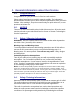
1. General Information about the FireLine 1.1. Congratulations! Congratulations on your purchase of a FireLine radio modem. Please take a few minutes to read this manual carefully. The information presented here will allow you to derive maximum performance from your radio modem. After reading it, keep the manual handy for quick reference, in case questions arise later on. 1.2. NOTICE There are no user-serviceable points inside this transceiver.
separation distance of following range. Failure to observe these restrictions may result in exceeding the FCC RF exposure limits. Antenna Installation: For rear deck trunk installation, the antenna must be located at least the following range away from rear seat passengers and bystanders in order to comply with the FCC RF exposure requirements. For Model RV-M5-VB-N2: Radiated frequency and Distance RV-M5-VB-N2 1.97 Feet (0.
1.5. FCC Compliance Information This device complies with part 15 of the FCC Rules. Operation is subject to the following two conditions: (1) This device may not cause harmful interference, and (2) this device must accept any interference received, including interference that may cause undesired operation. Changes or modifications not expressly approved by the party responsible for compliance could void the user’s authority to operate the equipment.
1.6. Overview The FireLine RF data radio is a rugged high-performance, high-speed narrowband data modem. It contains a receiver, a transmitter, and modem, creating an easy-to-use transparent data radio link. The FireLine’s user interface is asynchronous RS-232 data into and out of the FireLine (CMOS level optional). Modem operation is virtually transparent to the user and the configuration of the modem is via the user serial port.
2. Specifications 2.1. General All measurements made per TIA-603-B Size (inches)........................................................................................................................3.0D X 3.76W X 1.40H DC input voltage........................................................................................................................................9-16V DC Typical current draw, receiving, over-the-air rates < 4800bps................................................................
2.5. Frequencies The RV-M5-VB-N2 MURS modem has five user selectable channels. The channel is selected with the ATHP command. The RV-M5-VB-N2 modem is factory-set to these five channels, and the modem cannot be programmed to operate on any frequency other than these five. 1 2 3 4 5 151.820 MHz 151.880 MHz 151.940 MHz 154.570 MHz 154.
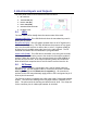
3. Electrical Inputs and Outputs The front panel of the FireLine modem has these features: 1. RF connector 2. Transmit LED (TX) 3. Receive LED (RX) 4. Power LED (PWR) 5. 9-Pin Serial I/O connector 6. DC Power Jack 3.1. LEDs The three status LEDs visually show the current status of the radio. Transmit LED (TX) This LED blinks red when the transmitter keys and is putting out RF power. Receive LED (RX) This LED glows red when there is an RF signal on the radio’s receive frequency.
3.3. Serial I/O Connector The 9-pin serial I/O connector is a female 9-p D-subminiature connector having the following pins configuration. Front-view of DB-9 connector on modem (female) Pin # Name Dir Function Level / Specification 1 CD out Carrier detect 2 3 4 5 RxD TxD DTR GND out in in Receive data Transmit data Data terminal ready Ground connection 6 DSR If enabled, indicates presence of carrier. 0 means carrier is present.
4. Using the FireLine Modem – Packet Mode This section describes the operation of the when it is in the Packet Mode of operation. Packet Mode is the factory-default operating mode. It is the easiest and most reliable mode of operation for a modem. Note: The configuration of the FireLine is done when the FireLine is in the “Command Mode”. Refer to Section 6 on page 25 for details on all of the available commands and programmable features.
Figure 1 (Packet Mode of Operation) For operation of the modem in the streaming data, non-packetized mode, see the section Streaming Mode on page 21. The Packet or Streaming operation is configured using the ATMT command, with Packet Mode being the factory default. 4.1. Setup 1. Connect a DC power source to the DC IN connection on the front of the modem. 2. Connect a good quality antenna, cut to the operating frequency, to the BNC connector on the front of the modem.
ATFX Frequency for this channel. Set to your frequency. ATMT 0 0 for normal Packetized operation. Default mode. ATAK 0 for no ARQ, 1 if this unit sends ACKs. Default is no ARQ. ATRB Set the number of retries if ARQ is used (x). 0 if no ARQ used. Factory default is no ARQ. ATBD Serial port baud rate ATMY The ID of this unit. Default is 1234. ATMK The network address mask. Default is FFFF. ATDT The address of the unit this modem will talk to. Default is 1234. ATBC Enable/disable busy channel lock-out.
In Packet Mode, selection of the serial port baud-rate is important. As shown in Figure 1 (Packet Mode of Operation) above, if the serial port baud-rate is the same as the over-the-air baud rate and the packets are short, the channel utilization is only about 50%. But, if the serial port baud rate is set much higher, say 2-8X the over-the air rate, the channel utilization becomes near 100%.
stop the modem from transmitting. The threshold where the FireLine senses RF carrier, and determines that the channel is busy is set by the ATRA command. This is factory calibrated to an equivalent RF level of approximately -110dBm. 4.4. Data Reception When the modem receives data over the radio, it checks it for errors, and if it is error-free, it will send it out the serial port.
Hexadecimal Numbers For those not familiar with hexadecimal numbers, a hexadecimal digit represents a 4-bit binary pattern. There are 16 possible values (0,1,2,3,4,5,6,7,8,9,A,B,C,D,E,and F). These 16 values represent 4 bits of information, thus 4 hexadecimal digits can represent 16 bits of information.
any modem with a unit ID 1200 through 12FF. Sending data with a destination ID of FF34 will be received by any modem with a unit ID of 0034 through FF34. The Address Mask The reason to use hexadecimal digits to represent the unit address, is that along with the Unit Address programmed into the FireLine, there is an “Address Mask” programmed into it. The default mask is FFFF. The address mask is also used to determine if a particular data transmission should be received by the modem.
Addressing Examples: Example 1 (default configuration) Sending Destination Address = 1234 Receiving Unit Address = 1234 Receiving Unit’s Address Mask = FFFF Result: Unit will receive the data, because the addresses identically match. When the addresses are identical, the value of the mask is not important. Notes: This is the default configuration. All units have address 1234, and all modems will talk to all other modems with address 1234.
and the sending station will automatically re-send the data. There are two aspects to configuring ARQ: 1) Enable the ARQ mode in the modem to allow it to transmit ACKs (ATAK 1 command). This command enables the modem to transmit ACK packets. 2) Configure the number of retries the modem should attempt if an ACK packet is not received back when it sends data (ATRB xx command). For example, if you set ATRB to 5 with the ATRB 5 command, the modem will wait for an ACK whenever it sends data.
Using the FireLine Modem – Streaming Mode This section describes the operation of the Streaming Mode of operation. This mode is selected with the command ATMT 2. 4.7. Streaming Mode Operation In Streaming Mode, radio transmissions will begin whenever data enters the mode, and the transmission will continue as long as there is data to send. The transmitter will automatically key when data enters the modem, and there is no need to assert any control lines.
and send it out over the air in the same order as it enters the modem. When the buffer is empty and there is no more data coming into the modem, it will automatically de-key the radio and go back into the receive mode. The FireLine modem will send a hidden end-of-message signal to the receiving modem, thus avoiding any extra data bytes “dribble bytes” from coming out of the user serial port.
4.11. Serial Data Flow Control If large amounts of data will be sent with the FireLine, and the serial port is operated at a faster data rate than the over-the-air rate, it may be possible to overflow the internal data buffer. To ensure the transmit buffer does not overflow, enable and use hardware flow control. Hardware flow control is enabled with the ATCH 1 command. Note that the FireLine modem will always indicate the status of its internal buffer using the CTS signal on the DB-9 serial connector.
5. Installation 1. Secure the FireLine modem using the four mounting holes on the side flanges of the unit. 2. Connect a DC power source to the DC IN connection on the front of the modem. Use the supplied cable, and connect the RED wire to +, and the black wire to – (ground). The black wire and the case of the FireLine should be connected to earth ground. 3. Connect a good quality antenna, tuned to the operating frequency, to the RF connector on the front of the modem.
6. User Serial Port Commands 6.1. Overview The asynchronous serial portion the RF modem is used to send and receive data over the air, as well as to configure the RF modem. In normal operation, the user sends data into the TxD pin of the user port, and this data is transmitted over the air. Received data from another RF modem is output to the user via the RxD pin of the user port. This is the default operating condition of the RF modem.
Once a Parameter is changed, the modem will begin using the new parameter as soon as it exits the Command Mode and returns to its normal operation mode. If the new parameter was saved to non-volatile memory using the ATSV command, then the new parameter will be used as well the next time the FireLine modem is powered on.
The default setting that the modem will revert to when the CONFIG button is pressed are: 1. Serial port 9600 baud, 8 data bits 1 stop, no parity 2. ATCT setting set to 60000 (60 second time-out) Even though the serial baud rate reverts to 9600 baud when the CONFIG button is pressed, it will revert back to the ATBD setting programmed into the modem once the Command Mode is exited. 6.6. Exiting the Command Mode There are three ways to exit the command mode. They are: 1.
6.8. AT Command Command Mode Commands Command Description Parameters Factory Default AK Enable/Disable ARQ – When ARQ is enabled, this modem will automatically send an ACK packet back to a modem that sends it data. 0=off, 1=on. Range: 0 – 1 AS Auto Status Report Interval– Sets the time between auto status reports. Time is in minutes. 0 means disabled. Range: 0 –56000 (minutes) 0 (Off) AT Silence AFTER Sequence - Sets period of silence after the command sequence characters in mS.
FF is interpreted as a group. See addressing section. MK MT MY NB NS PE R0 Address Mask – Configures local and global address space. Each digit may be a 0,1,2,3,4,5,6,7,8,9,A,B,C,D,E,or F. In most applications, this is kept at FFFF. Protocol Select – The over-the-air communication protocol. 0=Packetized mode, 2=Streaming data. Unit Address – Configures the individual; address for this unit. Each digit may be a 0,1,2,3,4,5,6,7,8,9,A,B,C,D,E,or F. Note: FF is interpreted as a group.
RS SL RSSI (Receive Signal Strength Indicator) – Returns the signal level of last received packet. This is DAC reading of the RSSI in the radio. It is not calibrated, but gives a relative signal strength indication. No parameters. Returns a number 0-1024. Serial Number – Reads and returns a unique serial number for thjs unit. Read Only 1 - 999999999 none unique SH Show – Display the configuration of the modem. This will return a page of ASCII characters, showing the main configuration parameters.
6.9. Setting the Over-The-Air Data Rate The SkyLine has programmable over-the-air baud rates. The over-the-air rate is stored in register R2, and is programmed with the ATR2 x command, where x is a number corresponding to the rate. The are 8 possible baud rates, but not all rates may be used with all radio modem models. Consult the following table.
6 = Enable the test points on the PCB. 7 = Transmit CW on center of channel 8 = Transmit preamble (101010 pattern) SHOW Display an overview of the configuration. ATST Display statistics of how the modem is working. AT$5 Display RSSI. It will scroll the reading until another character comes in the serial port. Packet Counter The packet counter mode will output packet count statistics once per minute. It will output the number of packets received in the last minute as well as the running total.
7. FireLine Diagnostic Provisions 7.1. Overview of Diagnostics Internal to the FireLine radio modem, is a powerful 32-bit microprocessor. Along with handing all aspects of radio modulation and demodulation, the microprocessor also maintains an extensive array of diagnostic information. This section details the diagnostic information available, and describes how to us the information to optimize or troubleshoot a FireLine radio network. 7.2.
7.4.
7.6. ATST3 Command The ATST3 command, will return the time and date the firmware in the FireLine was compiled. 7.7. ATST4 Command The ATST4 command will return internal timers that tell how long the modem has been powered up and running. All of these timers restart a 0 upon power up. Run time: Years: nnn Days : nnn Hours: nnn Min: nnn Sec: nnn Uptime:nnn OK 7.8.
PRX The number of packets this modem has received. PTX The number of packets this modem has transmitted. The ID code that the status information is sent to, is set with the ATMA xxxx command. Whenever a status transmission is sent, the “TO ID” of the transmission is the address set using the ATMA command. This allows the system to be configured in a way the normal modem communications take place between the modems, and the status information only is delivered to modems that need to receive it.
8. Tune-up and Alignment Do not key the transmitter for more than 30 seconds out of every 300 seconds. The transmitter is rated at 10% duty cycle maximum. Radio calibration and alignment is performed using the ATRx commands. The FireLine modem has been factory calibrated, in should not require any recalibration when installed, or when changing frequency or channel. Unless the user is trained in radio test and calibration, the values stored in the R registers should not be modified.
2. Key the transmitter into a 50 ohm load using the ATTD 5 command. The unit will now transmit, and send a digital 0 continuously. This should be +2.0kHz in frequency for narrow-band radios (12.5kHz spaced channels) and +4.0kHz for wide-band (25kHz channels). 3. Adjust the deviation register setting so that the frequency deviation is correct. The deviation is set with a digital adjustment. Use the ATR0 command to read or set the deviation level. 8.4.
with a pre-set value, and if it is above this value, Carrier Detect is asserted. The pre-set value may be change with the ATRA command. When the modem is used in the Streaming Mode (non-packetized operation, you may wish to configure the modem to require RF carrier detect to be active for the modem to receive data. Use the ATRF command to enable/disable this feature. To set the RF carrier detect level, perform the following steps: 1. Generate a test signal, 1kHz tone, 1.
9. Antenna Information Key to a successful installation is the choice and installation of a good antenna system. A good quality antenna can more than double the range of a radio system. Properly locating the antenna is vital to creating a quality radio link, and a poor installation can decrease the range of the system by as much at 90%. Use these guidelines to evaluate your antenna system design, and be sure contact a quality radio communication equipment distributor such as Talley Electronics (http://www.
10. Appendix A. Serial Port Hardware 10.1. Serial Port Data and Handshaking Signals In computer terminology, the RF modem is considered a “Data Communications Equipment” device, or DCE. The user’s hardware that the modem is connected to is considered “Data Terminal Equipment”, or DTE. Following is a description of how data and control is communicated over the various serial port signals between the modem (DCE) and another device (DTE) that the modem’s I/O port is connected to.
the user is send data into the modem at 9600 baud, the modem will negate the CTS signal once the FireLine’s internal data buffers become full. CD On this line the modem indicates to the DTE that it has received a carrier from a remote device. It will assert this signal any time there is a carrier detected. The modem may be configured to assert this when an RF carrier is detected (any onchannel RF, voice or data), assert it only when another RF modem signal is detected, or always assert it.
10.2. Null modem without handshaking Sometimes, a “Null Modem” cable may be required to connect the FireLine modem to another device. The specific connections are very dependent upon the type of hardware and handshaking used, but the following sections should help in configuring a null-modem cable. How to use the handshaking lines in a null modem configuration? The simplest way is to don't use them at all.
10.4. Null modem with full handshaking In this null modem cable, seven wires are present. The cable is shown in the following figure. Null modem with full handshaking (DB-9 Female shown. Same wiring for male-to-male cable) 10.5. Connector 1 Connector 2 Function 2 3 Rx Tx 3 2 Tx Rx 4 6 DTR DSR 5 5 Signal ground 6 4 DSR DTR 7 8 RTS CTS 8 7 CTS RTS Compatibility issues The null modem cable with full handshaking does not permit the older way of flow control to take place.
11. Troubleshooting Symptom: Unit will not receive Solution #1. Verify that the modem is on the correct RF channel. If it is, the RX LED should blink every time another modem tries to transmit to it. If the RX LED does not blink when it should be receiving, it is on the wrong RF frequency. Soultion #2. If the addresses match, and RX LED blinks but still no reception of data, verify that the RTS signal is asserted.
Solution #2. Handshaking. You may have hardware handshaking enabled on your terminal program, but the hardware or cable may not support it. Disable hardware handshaking on your terminal program to verify this is the issue. Symptom: Modem appears dead. Solution #1. Verify the power is on. When the modem has good DC power, the PWR LED will blink once per second. If it is not blinking, either the modem does not have power, the modem is broken, or the LEDs have been disabled via the ATL0 command.
12. Mechanical Company Confidential 47 Raveon Technologies Corp.
13. Limited One Year Warranty If within one year from date of purchase, this product fails due to a defect in material or workmanship, Raveon Technologies, Incorporated will repair or replace it, at Raveon’s sole discretion. This warranty is extended to the original consumer purchaser only and is not transferable.