
User's Manual

3. Electrical Inputs and Outputs
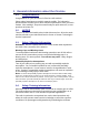
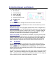
The front panel of the FireLine modem has these features:
1. RF connector
2. Transmit LED (TX)
3. Receive LED (RX)
4. Power LED (PWR)
5. 9-Pin Serial I/O connector
6. DC Power Jack
3.1. LEDs
The three status LEDs visually show the current status of the radio.
Transmit LED (TX) This LED blinks red when the transmitter keys and is
putting out RF power.
Receive LED (RX) This LED glows red when there is an RF signal on the
radio’s receive frequency. This LED will indicate the presence of any signal,
even one from other sources or radios, data, or voice. If it glows steadily at
all times, there is probably some other user on the radio channel. The RF
threshold level where this LED illuminates is programmable.
Power LED (PWR) This LED does a short blink, once every two seconds,
indicating to the user that the power to the modem is ON and the modem is
working. When the modem is in the command mode, this LED will blink on
and off, once per second. In the normal operating mode, this led will also
blink red with each reception when FireLine data is received over the air.
3.2. DC Power
DC power for the modem is connected to the 2-pin DC power input jack
labeled DC IN. Use the supplied cable to connect the DC power. The red
wire is positive (+) and the black wire is negative (-). Its connection is
optional, as the user may alternately apply power to Pin 9 and ground to pin 5
of the 9-pin I/O connector.
The FireLine modem is supplied with a DC power cable, Raveon part number
4C660. The connector housing on the DC power cable is a MOLEX 50-57-
9402. The pins used in the housing are MOLEX 16-02-1125. The crimp tool
for the connector pins is a Molex part number 11-01-0209.