
Specifications
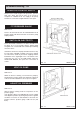


BEFORE REMOVING SERVICE ACCESS COVERS
ENSURE THAT ALL ELECTRICAL SUPPLIES TO THE
APPLIANCE HAVE BEEN TURNED OFF.
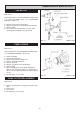
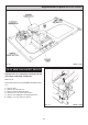
SEE FIG. 24
1. Open the controls door.
2. Remove thermostat control knob.
3. Remove 2 cover panel securing screws and remove
cover panel.
4. Remove the four control panel fixing screws.
5. Tilt the chassis forwards from the top and lift out. To
fully access the rear of the control chassis, the oven
thermostat capillary should be removed from the
oven. Follow instructions in section ‘TO FIT NEW
OVEN CONTROL’ thermostat, Steps 3 to 6.
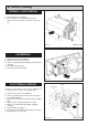
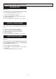
SWITCH OFF POWER TO THE APPLIANCE.
1. See Page 11 for removal of PCB.
2. Disconnect all the wires.
3. Fit wires to new PCB (wiring on Page 22).
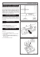
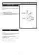
SWITCH OFF POWER TO THE APPLIANCE.
1. Access and Removal, see Page 12.
19
ELECTRICAL COMPONENT
ACCESS
Replacement of parts
(Electrical controls)
FIG. 24 DESN 514121
PCB REPLACEMENT
FAN REPLACEMENT