012WCA User manual
© Copyright 2013, Rayence Co. Ltd. All pages of this document contain proprietary and confidential information of Rayence Corporation and are intended for exclusive use by Rayence Corporation personnel or customers. Copying, disclosure to others or other use is prohibited without the express written authorization from Rayence Corporation. Please report any violations of requirement to Rayence Corporation.
Attention For improvement of product performance, supplementation, or follow-up of information; the contents of this manual are subject to change without separate prior notice. Please note that our company has neither responsibility for any accidents nor obligation to do free repair service for any damage of the equipment due to user's mistake, which resulted from failure to follow the contents in this manual. Make sure to be familiar with the safety precautions and usage procedures.
Contents 1. 2. 3. 4. 5. 6. 7. 8. 9. Introduction ....................................................................................1 (1) (2) (3) (4) (5) (6) (7) Overview ........................................................................................ 1 Intended use.................................................................................. 1 Product features ........................................................................... 2 Product components .............................
10. Maintenance .................................................................................81 (1) (2) (3) (4) (5) Maintenance ................................................................................81 Cleaning .......................................................................................81 Inspection ....................................................................................82 Disposal or Recycling ................................................................
1. Introduction (1) Overview The 1012WCA is a wireless digital X-ray flat panel detector that can generate images of any part of the body. The wireless LAN((IEEE 802.11a/g/n) communication feature improves the operability, and high-speed processing. This X-ray imaging system consists of a scintillator directly coupled to an a-Si TFT sensor. It makes high-resolution, high-sensitive digital images.
(3) Product features Wi-Fi (802.
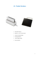
(4) Product components Photo Medical Image Processing Unit Item Quantity Detector 1 Handle 1 Battery pack 2 Battery charger 1 Charger adapter 1 AGI 1 3
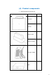
Cables Item Length Quantity Link cable 7m 1 PInterface cable 8m 1 USB cable(A to 1.8m B) 1 LAN cable 10m 1 AC Power 1.
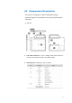
(5) Components Description The detector is designed to capture radiographic images. Captured images are transmitted to PC using the wireless/wired connection. (1) Detector 1. Link Cable Connector : Use for charging battery while detector is in use(Connect between detector and power supply) 2. LED indicator: Indicating the state of detector.
3. Power & Mode Sleep Button 4. Handle unlock-lever : This is an unlock-lever to remove handle. 5. Handle : Hold this handle when carrying the sensor unit. It is removable. (Horizon/Vertical) 6. CFRP(Carbon Fiber Reinforced Plastic) : The part of the patient’s body to which an image is to be taken should be placed against this plate. 7. Shock sensor : Detector has built-in 2 Shock sensors. It detects and records impact and mishandling of fragile 8.
(2) Battery & Charger 1. Battery : Rechargeable Lithium Ion battery(Charging Time-3 hrs) ※ In the diagram above, the box shows where the remaining battery percentage is displayed. 2. Battery Charger : Two port cradle type. 3.
※Wireless Module and Wireless Antenna Wireless antennas: The module adopts the latest 802.11n Dual-Band technology. DUT does not support simultaneous transmission. The transmitter of the module is powered by host equipment (Detector). The antennas are 2 printed-dipole and correlated antennas. Does not support beamforming.
This device complies with Industry Canada licence-exempt RSS standard(s). Operation is subject to the following two conditions: (1) this device may not cause interference, and (2) this device must accept any interference, including interference that may cause undesired operation of the device. Le present appareil est conforme aux CNR d'Industrie Canada applicables aux appareils radio exempts de licence.
(6) Warning Make sure to observe the following right Environment of Use and Storage Follow the specified process of operational instructions written in this manual for the safety of the users and patients. Does not use or store the instrument near any flammable chemicals such as thinner, benzene, etc. Also, this instrument is not a category AP or APG equipment. If chemicals are spilled or evaporate, it may result in fire or electric shock through contact with electric parts inside the instruments.
Never disassemble or modify the product as it may result in fire or electric shock. Also, since the instrument incorporates parts that may cause electric shocks and other hazardous parts, touching them may cause death or serious injury. Do not hit or drop the instrument. The instrument may be damaged if it receives a strong jolt, which may result in fire or electric shock if the instrument is used without being repaired.
(7) Caution Environment of Use and Storage Do not install the instrument in a location with the conditions listed below. Otherwise, it may result in failure or malfunction, cause fire or injury. Close to facilities where water is used. Where it will be exposed to direct sunlight. Close to air-conditioner or ventilation equipment. Close to heat source such as a heater. Prone to vibration. Insecure place. Dusty environment. Saline or sulfurous environment.
Handling Do not spill liquid or chemicals onto the instrument or, in cases where the patient is injured, allow it to become wet with blood or other body fluids, as doing so may result in fire or electric shock. In such situation, protect the instrument with disposable covering as necessary. Wipe the CFRP plate of the sensor unit with ethanol or glutaraldehyde solution to disinfect it each time a different patient uses the instrument, in order to prevent infection.
Do not place your battery in or near a heat source. Excessive heating can damage the detector or the battery and could cause the detector or the battery to explode. Do not dry a wet or damp battery with an appliance or heat source such as a microwave oven, hair dryer, iron, or radiator. Do not dispose of the detector or the battery in a fire. The detector or the battery may explode when overheated. Never use any charger or battery that is damaged in any way.
2. Notes for Using the Detector (1) Preparing Fully charge the battery pack. Charge the battery on the day of examination or on the previous day. Battery slowly discharges even of not in use. The battery pack may have expired if it discharges immediately after being fully charged. You can purchase an optional battery pack to replace an exhausted one. Be sure to fully charge the battery before use. ※ The battery charger, RC120W is designed for the dedicated battery pack.
(2) Handling Handle the instrument carefully, as it may be damaged if something is hit against it, dropped, or receives a strong jolt. (3) Handle Assembly A B ※ Insert the handle always in the same direction.
Handle Assembly Type 1 Please confirm lever position. When the handle is locked, the lever should be same position with the right picture. A Insert the handle in the same direction If the handle is not locked, the detector can be dropped. Handle Assembly Type 2 (4) Before Exposure Be sure to check the equipment daily and confirm that it works properly. Sudden heating of the room in cold areas will cause condensation to form on the instrument.
room and in the instrument does not occur, to prevent forming of condensation. (5) During Exposure Do not use the detector near devices generating a strong magnetic field. Doing so may produce image noise or artifacts. Do not apply excessive weight to the sensor unit. Otherwise, the sensor may be damaged.
(6) Limit of Load Uniform load: 150 kg over the whole area of sensor window. Local load: 100 kg on an area 40 mm in diameter.
Be sure to use the sensor unit on a flat place so it will not bend. Otherwise, the sensor may be damaged. (7) Disinfection and Cleaning Do not spray the detector directly with disinfectants or detergents. Do not use anything other than neutral detergent for cleaning the cover of the instrument. Otherwise, the coating will be corroded. (8) Others Be sure to reconnect the cables to the proper connectors. Otherwise, the instrument may malfunction or may be damaged.
3. Technical Features (1) Mechanical Features Size 395 x 337 x 18 mm Weight 2.7 kg (not incl. Handle) Encapsulation Material Mg Window Material Carbon fiber plate with 1.5mm thickness (2) Electrical Features Detector Sensor Type Amorphous Silicon with TFT (Single Panel) X-ray Converter CsI:Tl Total Pixel Number 2560 × 2048 pixels Total Pixel Area 325 x 260 mm Effective Pixel Number 2520 × 2008 pixels Effective Pixel Area 320 x 255 mm Pixel Pitch 127 μm Limiting Resolution Max. 3.
Capacity The number of times being acquired image Typ. 3400 mAh 1060 images (@cycle time = 15s) The Battery level can be displayed on the LED status of battery. If the battery level goes down under 25%, please charge the battery Battery level Display 75~100 % 50~75 % 25~50 % 0~25 % Charger Size 267.5 x 100 x 77 mm Weight Typ. 0.7 kg Input 20 VDC Output 12.6 VDC Adapter Size 160 x 76 x 43.7mm (cable length: 1.28m) Weight Typ. 0.8 kg Input 100~240 VAC, 47~63 Hz, 1.4~0.
Wireless Spec 802.11a/g/n compliance Standard Without DFS (5.25GH to 5.35GHz and 5.47 to 5.725) Band Peak Rate 300Mbps Frequency 2.4 GHz / 5 GHz Bandwidth 20MHz/40MHz MIMO 2x2 ※ Maximum wireless signal rate derived from IEEE standard specifications. Actual data throughput will Network conditions and environmental factors, including volume of network traffic, building materials and construction, and network overhead, lower actual data throughput rate.
(3) Environmental requirement Item Temperature (Storage) Temperature (Operation) Humidity (Storage) Humidity (Operation) Vibrations (Wrapping condition) Min. Typ. Max. Unit -10 50 ℃ 5 40 ℃ 10 80 30 75 Note % H.R. % H.R. 10-150Hz, 2G 10Sweeps, (8G) 1min/Octave, XYZ axis ※ Regularly changed parts : Battery (warranty 6 months) (4) PC Requirements Processor: At least Intel Pentium IV HT with 2.
4. Installation The Detector is composed of sensitive electronic parts and Portable Imaging processing unit must be installed in a way that enables the user to achieve optimal use components. It is recommended to use the product in a clean place and to exercise caution to ensure that it is not affected by dust or liquids. It is recommended to Use a dry and soft cloth to clean the detector housing. (1) Program setup Detector’s IP : Wireless - 2.2.2.100 Wired – 2.2.2.
(2) Connection (Manual Trigger) Power Connection A. Connect the battery pack or power cable to the equipment. * In wired mode, the frame ground is necessary. * When you use the detector with wired mode, the WLAN function is automatically off. B. Connect the USB cable from your PC to AGI. ※ Be sure to sure only the dedicated battery pack, RB37WH for 1012WCA.
Wireless Communication A. AP Router(Line sharer) setting - SSID : Griffon - Internal network - IP address : 2.2.2.1 - Subnet mask : 255.255.255.0 - Dynamic IP allocation range : 2.2.2.2~2.2.2.254 - Pre-Shared Key(Password) : project302 - Authentication methods : WPAPSK or WPA2PSK - Password methods : TKIP/AES - AP IP : 2.2.2.
C. Checking Link Quality & Battery Remain - After wireless connection is established, perform ‘Get Image’ in ‘Calibration & Acquisition’ tap. - Check the value named ‘Wireless Signal’ in black log screen. Wireless Signal = Link Quality (Max. 100) - Check the value named ‘Battery Remain’ in black log screen. Battery Remain = Battery Remain(Max.
Software Setting (manual trigger) Figure 2: Davinci Setting 29
Trigger Connection A. Connect the P-interface cable or trigger cable to the generator X-ray Generator Connection Make assurance doubly sure SIGNAL RATING before connection. A. Mode 1 : P-interface cable mode Connect the P-interface cable between the AGI box and X-ray generator.
The window time can be changed. Refer to the following pictures Exposure Time 500msec is designate to 0.
B. Mode 2 : Trigger cable mode Connect the Trigger cable between the X-ray enable connector of Make assurance doubly sure SIGNAL RATING before connection. AGI with X-ray generator. AGI Box Figure 8: <2nd example> wiring for the interface between portable generator & detector Connection description Signal New Label Old Label Color Input / Output 12V~24VDC R.E.C.
Operating description Figure 3 : Timing chart t1: It will be occurred when exposure switch is pushed completely after. t2: Window time of detector is varying 0 sec ~ 5 sec. which can be control by S/W. (Editing parameter: Exposure Time – Refer to the NOTE) Expose relay switch ON time (Window Time) and X-ray exposure time must be same. t2 time can be control by S/W The window time can be changed. Refer to the following pictures Exposure Time 500msec is designate to 0.
(3) Connection (Auto Trigger) Power Connection A. Connect the battery pack or power cable to the equipment. * In wired mode, the frame ground is necessary. ※ Be sure to sure only the dedicated battery pack, RB37WH for 1012WCA.
Wireless Communication A. AP Router(Line sharer) setting - SSID : Griffon - Internal network - IP address : 2.2.2.1 - Subnet mask : 255.255.255.0 - Dynamic IP allocation range : 2.2.2.2~2.2.2.254 - Pre-Shared Key(Password) : project302 - Authentication methods : WPAPSK or WPA2PSK - Password methods : TKIP/AES - AP IP : 2.2.2.
C. Checking Link Quality & Battery Remain - After wireless connection is established, perform ‘Get Image’ in ‘Calibration & Acquisition’ tap. - Check the value named ‘Wireless Signal’ in black log screen. Wireless Signal = Link Quality (Max. 100) - Check the value named ‘Battery Remain’ in black log screen. Battery Remain = Battery Remain(Max.
Software Setting (Auto trigger) Figure 4: Davinci Setting 37
Important Note In AUTO TRIGGER MODE, the trigger will be forced not to acquire images when detector senses vibration or shock. In READY mode, Detector will automatically switch to WAIT mode when detector senses vibration or shock, so that user won’t acquire images in WAIT mode although X-ray exposure applies. WAIT mode switches back to READY mode after 2-3 seconds.
(5) IP set up [My Network Places] → [Properties] → [Local Area Connection] → [Properties] → [Internet Protocol (TCP/IP)] → [Use the following IP address] IP address: Obtain an IP address automatically IP address : Obtain an IP address automatically 39
(6) Using FPD_Manager (IP, SSID Change / Upgrade FW) Change IP Address of Detector A. Turn on Detector and connect to PC (wired connection is recommended) B. After detector boot up, Launch FPD_Manager.
C. Check the “IP Change” and type current IP address as below D.
E. Click “Start Setting” button F. Click “예 (Y) ” button G. Click “확인” button H.
Change SSID and PSK(Pre-Shared Key) A. Turn on Detector and connect to PC (wired connection is recommended) B. After detector boot up, Launch FPD_Manager.
C. Check the “SSID change” and write current IP address as below D.
E. Click “Start Setting” button I. Click “예 (Y) ” button F. Click “확인” button G.
Upgrade Firmware A. Turn on Detector and connect to PC (wired connection is recommended) B. After detector boot up, Launch FPD_Manager.
C. Check the “SSID change” and write current IP address as below D. Select firmware or FPGA file by click “select” button .
E. Click “Start Setting” button F. Click “예 (Y) ” button G. Click “확인” button H.
5. Calibration X-ray detector should be used at stable state within driving temperature range. Acquire the X-ray images after power on and 5 minutes warming up to obtain high quality images. (1) General Principle Notation Calibration can be done by image acquisition S/W. The gainoffset correction (under calibration) will be done with one dark, at least one bright and object frame.
Bright Calibration Point The calibration range of bright is can be select by which exposure level is maximum level that user want to use. If the maximum level of user want to use is ‘6500’ in this case the level is contained in Bright point of ‘3’(refer ‘Table 5 : Median value’). The meaning is you don’t have to make bright point for ‘4’(In this case, it will be does not working if you get image on higher level than maximum bright point.) To gain correction, bright frame and dark frame should be acquired.
(2) Calibration (Manual mode) Describe the calibration step by step. 1st Step A. Push “Calibration” button B.
C. Click on the “Calibration” button. The acquired dark frame “dark.raw” will be generated in the “\cal\” folder.
Click button [Get Bright]. It will produce frame with name %CAL% xNNNNNA.raw, where NNNNN is median pixel’s value within current image borders after offset calibration (cut frame edges are never used during calibration). Suffix ‘A’ (it also could be ‘B’,’C’ etc) avoids casual coincidence of file names. 2nd Step Push “Get Bright” button at different four of X-ray condition. The X-ray condition should be set or tested before, same as the level of ‘1.2’.
3rd step After 2nd step, the “Generate” button will be activated. Click the button “Generate”, and then calibration point will be generated which of file name is “A ‘# of point’_ ‘median value of generated point’” like file of bright frame. The acquired bright frames within tolerance value which is variance of median level of acquired bright frames will be averaged and generated to a calibration point. The tolerance value can be edited.
4th step After 3rd step, Change Bad Pixels Removal Tab, Click the button “Generate Auto BPM”, and then Defect Map will be generated which of file name is “BPM.raw “ at the “\cal\” folder.
5th step For additional Defect correction, if “BPMM.raw” is existed at the install CD, copy to the “\cal\” folder. 6th step On Acquisition Tab. Check the box “Offset Calibration”, “Gain Calibration”, “Bad Pix Map” for activate to each calibration and Bad Pixels Removal. Otherwise, it will does not working when going to pre-processing .
(3) Calibration (Auto mode) Describe the calibration step by step. 1st Step A.
B. Click “Start” button to acquire a dark frame then “dark.raw” will be generated in the “\cal\” folder. Figure 2: Auto calibration start C.
D. When ‘Bright acquiring bright frame’ is shown, Exposure X-ray to create Bright points as RED box on ‘Figure 4’ bright point made by average value of 4 bright frames in same condition, therefore, 16frames will be needed to make 4 bright points Suitability of the acquired bright frames are shown at the message box as ‘figure 5’, please check the message box for each steps.
Figure 5 Bright acquisition message Figure 6 Calibration complete 60
2nd step For additional Defect correction, if “BPMM.raw” is existed at the install CD, copy to the “\cal\” folder. 3rd step On Acquisition Tab. Check the box “Offset Calibration”, “Gain Calibration”, “Bad Pix Map” for activate to each calibration and Bad Pixels Removal. Otherwise, it will does not working when going to pre-processing .
6. Image Acquisition Test (1) Get Image On Acquisition tab, click the “Get Image” button to get image. After click the button, you can see pop-up window, which is display window time and process of acquiring image.
(2) View Images Frame- and image-files have extension “raw” and contain pixel data in signed 16-bits little-endian format. One could view those files in Photoshop or another image editor.
Common controls and displayed statistics Pixel_Min – minimum pixel value in frame- or image- data Pixel_Max – maximum pixel value Pixel_Black – if a pixel ≤ Pixel_Black then it is displayed as black (RGB 0, 0, 0) Pixel_White – if a pixel ≥ Pixel_Black then it is displayed as black (RGB 255, 255, 255) 64
Histogram’s presentation Relative Histogram Scale [H]=1000 means that that the distance depicted as “H” on the drawing matches 1% of total number of pixels. Respectively [H]=100 means that “H” matches 0.1% of pixels and [H]=500 means that “H” matches 0.5% of pixels.
Marker type “S” Displays local surround of selected location Marker type “R” Display profile chart of a row.
Marker type “C” Display profile chart of a column.
(3) Get Recent Frame If the image is not transferred to the PC after exposure because of connection fail (wire or wireless). You can get a recent frame again. .
7. Operation (1) Recommend X-ray detector should be used at stable state within driving temperature range. Acquire the X-ray images after power on and 5 minutes warming up to obtain high quality images. The calibration should be performed every 6 months (2) Switching power on / off All connection should be done, before turn on the power. Press the power button by more than 3 sec, when power on/off. The green light of the LED indicator on the detector is on, the detector power is on.
8. Safety Information (1) Safety standard Do not touch signal input, signal output or other connectors, and the patient simultaneously. External equipment intended for connection to signal input, signal output or other connectors, shall comply with relevant IEC Standard. This equipment has been tested and found to comply with the limits for medical devices in IEC 60601-1-2:1994. These limits are designed to provide reasonable protection against harmful interference in a typical medical installation.
Type of protection against electric shock: Class I equipment Classification according to the degree of protection against ingress of water as detailed in the current edition of IEC 529: IPX0, ordinary equipment This equipment is not suitable for use in the presence of flammable anesthetic s or oxygen.
(2) Electromagnetic Compatibility Information Guidance and manufacturer’s declaration - electromagnetic emissions The EUT is intended for use in the electromagnetic environment specified below. The customer or the user of the EUT should assure that it is used in such an environment. Immunity Test RF Emissions CISPR 11 Compliance Group 1 Electromagnetic Environment - Guidance The EUT uses RF energy only for its internal function.
Guidance and manufacturer’s declaration - electromagnetic immunity The EUT is intended for use in the electromagnetic environment specified below. The customer or the user of the EUT should assure that it is used in such an environment. The EUT is intended for use in the electromagnetic environment specified below. The customer or the user of the EUT should assure that it is used in such an environment.
Guidance and manufacturer’s declaration - electromagnetic immunity The EUT is intended for use in the electromagnetic environment specified below. The customer or the user of the EUT should assure that it is used in such an environment.
Recommended separation distances communications equipment and the EUT between portable and mobile RF There is intended for use in an electromagnetic environment in which radiated RF disturbances are controlled. The customer or the user of the EUT can help Prevent electromagnetic interference by maintaining a minimum distance between portable and mobile RF communications equipment (transmitters) and the EUT as recommended below, according to the maximum output power of the communications equipment.
Immunity and Compliance Level Immunity test IEC 60601-1-2 Test Level Actual Immunity Level Compliance Level Conducted RF IEC 61000-4-6 3Vrms 150kHz to 80MHz 3Vrms 3Vrms Radiated RF IEC 61000-4-3 3Vrms 80MHz to 2.5GHz 3V/m 3V/m Guidance and manufacturer’s declaration - electromagnetic immunity The EUT is intended for use in the electromagnetic environment specified below. The customer or the user of the EUT should assure that it is used in such an electromagnetic environment.
9. Radio Frequency compliance (1) FCC Notice (U.S.A) Test standards - 47CFR Part 15.107 (b) / 47CFR Part 15.109 (g) Class A. - FCC Part 15 C Section 15.247, Operation within the bands 902–928 MHz, 2400–2483.5 MHz, and 5725–5850 MHz - FCC Part 15 C Section 15.407, Operation within the bands 902–928 MHz, 2400–2483.5 MHz, and 5725–5850 MHz FCC ID: QIIRY1012WCA 5.15- 5.25 GHz band is restricted to indoor operations only.
FCC CAUTION Changes or modifications not expressly approved by the party responsible for compliance could void the user’s authority to operate the equipment. This transmitter must not be co-located or operated in conjunction with any other antenna or transmitter. When installing it in a mobile equipment This equipment complies with FCC radiation exposure limits set forth for an uncontrolled environment and meets the FCC radio frequency (RF) Exposure Guidelines in Supplement C to OET65.
(2) IC Notice (CANADA) Test standards - ICES-003 Issue 4 - IC RSS-210 Issue 7, Operation within the bands 902–928MHz, 2400–2483.5 MHz, and 5725–5850 MHz - IC RSS-210 Issue 7, Operation within the bands 902–928 MHz, 2400–2483.5 MHz, and 5725–5850 MHz IC: 10742A-1012WCA This Class A digital apparatus complies with Canadian ICES-003 Host device of the approved module shall be marked with the following item: This device complies with Industry Canada licence-exempt RSS standard(s).
(3) R&TTE Notice (European Union) Test standards - EN 62311 - ETSI EN 301 489-1 - ETSI EN 301 489-17 - ETSI EN 300 328 - ETSI EN 301 893 80
10. Maintenance (1) Maintenance For safety reasons, be sure to turn OFF the power of the detector when the following inspections are going to be performed. Otherwise, it may result in electric shock. Maintenance of the detector should be done by an authorized service provider If the Detector Panel is defective, the detector will be returned as is to the manufacturer for repair Clean the equipment with a dry soft cloth, or a soft cloth lightly moistened with mild detergent solution.
(3) Inspection In order to ensure that the instrument is used safely and normally, please be sure to inspect the instrument before use. If any problem is found during the inspection, please take measures indicated in this chapter. If problem still cannot be corrected, please contact Rayence representative or distributor. It is recommended that a record of the inspection be kept by making copies of the check lists in this section, or making a separate check list.
(4) Disposal or Recycling Follow local governing ordinances and recycling plans regarding the disposal or recycling of device components. Disposal of old Electrical & Electronic Equipment (Application in the European Union and other European countries with separate collection system.) This symbol indicates that this product shall not be treated as household waste. Instead, it shall be handed over to the applicable collection point for the recycling of electrical and electronic equipment.
(5) Marking and labeling symbols Symbols Meaning Refer to instruction manual/ booklet Alternate current Protective earth (Ground) Off (power : disconnect from the main switch) On (power : connect to the main switch) Warning Caution Read carefully Manufacturer Date of manufacture Serial number 84
non-ionizing radiation WEEE : Waste Electrical and Electronic Equipment Authorized representative in the European Community CE symbol grants the product compliance to the European Directive for Medical Devices 93/42/EEC as a class Ⅱa device. Authorized by Notified Body SGS (code no.
Appendix Dimension [unit : mm] 86
Rayence Co., Ltd. 14, Samsung 1-ro 1-gil, Hwaseong-si, Gyeonggi-do, Korea www.rayence.