G-Series Systems Installation and Commissioning Instructions
G-Series System Installation & Commissioning Instructions Document Number:87070_1 Date: June 2007
Trademarks and registered trademarks Autohelm, HSB, Raymarine, RayTech, Sail Pilot, SeaTalk and Sportpilot are registered trademarks of Raymarine Limited. Apelco is a registered trademark of Raymarine Holdings Limited (Registered in all major marketing territories). AST, Autoadapt, Auto GST, Autoseastate, Autotrim, Bidata, Marine Intelligence, Maxiview, On Board, Raychart, Raynav, Raypilot, Raystar, ST40, ST60, Seaclutter, Smart Route, Tridata and Waypoint Navigation are trademarks of Raymarine Limited.
Contents Chapter 5: Installation and mounting ................ 57 5.1 General instructions .................................................58 5.2 GPM400 Processor module .....................................59 5.3 G-Series Keyboard ...................................................60 5.4 G-Series Monitors ....................................................65 5.5 GVM400 Video Module ............................................66 5.6 Alarm buzzer ...........................................................
G-Series Installation & Commissioning 6
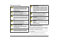
Warnings and cautions Navigation aid Raymarine equipment is intended for use only as an aid to navigation. You must still ensure that a properly qualified person is acting as navigator at all times and that all applicable maritime regulations are adhered to. You must also ensure that all proper judgements and actions are taken to ensure a safe passage.
Waste Electrical and Electronic Equipment Directive i. At least 3 ft. (1 m) from any equipment transmitting or cables carrying radio signals e.g. VHF radios, cables and antennas. In the case of SSB radios, the distance should be increased to 7 ft. (2 m). ii. More than 7 ft. (2 m) from the path of a radar beam. A radar beam can normally be assumed to spread 20 degrees above and below the radiating element. • The product is supplied from a separate battery from that used for engine start.
Disclaimer The technical and graphical information contained in this handbook, to the best of our knowledge, was correct as it went to press. However, our policy of continuous improvement and updating may change product specifications without prior notice. As a result, unavoidable differences between the product and handbook may occur from time to time. Raymarine cannot accept responsibility for any inaccuracies or omissions it may contain. For the latest product information visit our website - www.
G-Series Installation & Commissioning 10
Chapter 1: Introduction This guide provides information to help you plan, install and commission your G-Series system. Chapter contents • 1.1 Handbook information on page 12. • 1.2 Plan your installation on page 12. • 1.3 Install your system on page 12. • 1.4 Commissioning on page 13. See also You may require additional information when planning or installing your system. • Spares and accessories. Lists of spares, accessories and cables can be found in Appendix C - Spares and accessories.
1.1 Handbook information Nav Station details This document is part of a series of books associated with the GSeries system We strongly recommend that you produce a complete schematic diagram for your G-Series installation. See Appendix B - Nav Station schematic. All documents can be downloaded from: www.raymarine.com/handbooks. 1.
1.4 Commissioning Once you have completed the installation, proceed with the commissioning of the system: Tick Commissioning task Installation instructions Assign master GPM Chapter 7: Initial Setup Set up Nav Stations Chapter 7: Initial Setup Assign keyboards Chapter 7: Initial Setup Commission ancillary equipment Chapter 8: Commissioning Complete warranty cards for equipment installed Refer to separate warranty booklets supplied with equipment.
G-Series Installation & Commissioning 14
Chapter 2: Typical systems This section provides an overview of typical G-Series systems and ancillary equipment.
System overview SeaTalkng SeaTalkng instruments/pilot SeaTalkng Navstation 1 (e.g. Flybridge) GPM 400 DVI or VGA Monitor CANCEL ENTER CANCEL MENU ENTER MENU and/or SeaTalk instruments/pilot Keyboard 2 ABC 5 JKL 3 DEF 6 MNO WPTS PAGE MENU MOB OUT RANGE ENTER 7 8 9 PQRS TUV WXYZ . 0 IN ACTIVE DODGE DATA PILOT STANDBY OK CANCEL Navstation 2 (e.g.
Single processor system Navstation SeaTalkng backbone Monitor Keyboard 1 2 ABC Pilot 5 6 JKL MNO WPTS PAGE MENU MOB OUT RANGE 7 8 9 PQRS TUV WXYZ .
Dual Nav station (single processor) Navstation, (e.g. Flyridge) SeaTalkng backbone Monitor Pilot Keyboard 1 4 GHI 2 3 ABC DEF 5 6 JKL MNO WPTS PAGE MENU MOB Instrument OUT RANGE ENTER 7 8 9 PQRS TUV WXYZ . 0 IN ACTIVE DODGE DATA PILOT STANDBY OK CANCEL Wireless base station SeaTalkng CANCEL ENTER CANCEL MENU ENTER MENU SeaTalkng Monitor 1 2 ABC 4 GHI 5 JKL 3 DEF 6 MNO WPTS PAGE MENU MOB OUT RANGE ENTER 7 8 9 PQRS TUV WXYZ .
Network system, Single Nav station (Dual processor) SeaTalkng backbone Monitor SeaTalkng Instrument Keyboard 1 2 ABC 4 GHI 5 JKL 3 DEF 6 MNO WPTS PAGE MENU MOB 7 8 9 PQRS TUV WXYZ .
Dual Nav station (Dual processor 2) Navstation 1 (e.g. Bridge) Navstation 2 (e.g. Flybridge) Monitor 5 JKL 3 1 DEF 4 WPTS PAGE MENU MOB DODGE STANDBY PILOT OK CANCEL SeaTalkhs GPM400 (data master) 6 WPTS PAGE MENU MOB OUT RANGE 8 9 TUV WXYZ .
Entertainment system SeaTalkng backbone Plasma Television Basestation SeaTalkhs switch Video module Keyboard charge point 1 2 ABC 4 GHI 5 JKL 3 DEF 6 MNO WPTS PAGE MENU MOB OUT RANGE ENTER 7 8 9 PQRS TUV WXYZ .
System limits The following quantities of G-Series components may be connected within a single system: G-Series component Max. number on system GPM400 processor module 4 (of which 1 must be set as master GPM) Monitors 8 (2 per GPM400 processor) Keyboards 8 GVM400 video module 2 DSM digital sounder 1 Digital radar scanner 2 See also For limitations associated with ancilliary components and systems, refer to the separate manufacturer’s documentation.
Chapter 3: Packs and contents This section contains details of pack contents for the G-Series system components. Chapter contents • • • • • • • 3.1 GPM400 processor on page 24 3.2 GVM400 video module on page 25 3.3 G-Series Keyboard on page 26 3.4 Keyboard wireless upgrade kit on page 27 3.5 SeaTalkng wireless basestation on page 28 3.6 Marine monitors on page 28 3.7 Alarm buzzer on page 29 See also • For peripheral components (e.g.
3.1 GPM400 processor Pack items GPM400 Processor Module Description Part No. GPM400 Processor module - US version GPM400 Processor module - EU version GPM400 Processor module - ROW version E02042 E02047 E02048 1.5 m (4.9 ft) Power cable R08003 1.5 m (4.9 ft) NMEA 0183 cable R08004 1 m (3.3 ft) SeaTalkng spur cable A06039 1.5 m (4.9 ft) SeaTalk/Alarm Out cable E55054 3 m (9.
3.2 GVM400 video module Pack items Description Part No. GVM400 Video Module E02043 1.5 m (4.9 ft) S-Video cable R08274 1.5 m (4.
3.3 G-Series Keyboard Pack items Handbook/ Documentation Suncover Command center keyboard Panel seal Rear clamp assembly SeaTalkng T connector Stud (x4) Finger nut (x4) SeaTalkng backbone cable D10065-1 SeaTalkng spur cable G-Series Installation & Commissioning 26 Description Part No. G-Series command center keyboard E02044 Sun cover R08307 1 m (3.3 ft) SeaTalkng/NMEA2000 cable A06039 400 mm (15.
3.4 Keyboard wireless upgrade kit Pack items Battery pack Mounting plate Connector cover Allen head screw (x4) Allen key Screw (x3) Handset dust cover SeaTalkng bulkhead mounting cable Part No. SeaTalkng bulkhead mounting cable R08311 2.5 m (8.
3.5 SeaTalkng wireless basestation 3.6 Pack items Marine monitors Pack items SeaTalkng wireless basestation SeaTalk T connector Marine display Mounting brackets x 2 SeaTalkng backbone cable Sun cover SeaTalkng spur cable 5 meter VGA cable assembly Description Part No. Wireless basestation E02045 1 m (3.3 ft) SeaTalk NG spur cable - stripped ends A06043 400 mm (15.75 in) SeaTalkng backbone cable Description Part No.
3.7 Alarm buzzer D10363-1 Pack items Description Part No.
G-Series Installation & Commissioning 30
Chapter 4: Cables and connections This section contains details of cables and connections. Use it to plan your system wiring and ensure that you have the necessary cables available. Chapter contents • 4.1 General instructions on page 32 • 4.2 Power distribution on page 33 • 4.3 GPM400 processor on page 37 • 4.4 Monitor connections on page 38 • 4.5 Keyboard connections on page 40 • 4.6 Video and Entertainment on page 43 • 4.7 SeaTalkhs network on page 47 • 4.8 GPS Connection on page 49 • 4.
4.1 General instructions Strain relief • Cable types and length • Follow the guidelines given in this section to determine appropriate cable types and length. • Unless otherwise stated use only standard cables of the correct type, supplied by Raymarine. • Ensure that any non-Raymarine cables are of the correct quality and gauge. For example, longer power cable runs may require larger wire gauges to minimize any voltage drop in a cable.
4.2 Power distribution Typical distribution Monitor Monitor Radar GPS Distribution Panel DSM 400 GPM400 GPM400 +VE bar -VE bar All GPM400 processors must be powered from a single breaker. In line fuse protection must be provided for each individual power circuit.
Circuit grounding Power distribution notes: • Raymarine recommend that you have a dedicated distribution panel for your G-Series system. • All GPM400 processor units must be powered from a single breaker or switch, with appropriate circuit protection. • All monitors and ancillary equipment should where possible be wired to individual breakers. Grounding The power cable screen and all Ground terminals MUST be connected to ship’s ground.
Circuit protection Equipment Supply voltage Thermal breaker Fuse GVM400 Video Module 12 V 1.2 A 2A 24 V 1A 1A GPM400 processor All GPM400 processors must be switched via a single breaker.
GPM400 power cables Length (max) Supply voltage Cable gauge (AWG) 0-5 m (0-16.4 ft) 12 V 18 24 V 20 5-10 m (16.4-32.8 ft) 12 V 14 24 V 18 10-15 m (32.8-49.2 ft) 12 V 12 24 V 16 12 V 12 24 V 14 15-20 m (49.2-65.6 ft) Supply voltage 0-5 m (0-16.4 ft) 12 V 20 24 V 20 5-10 m (16.4-32.8 ft) 12 V 20 24 V 20 10-15 m (32.8-49.2 ft) 12 V 20 24 V 20 G-Series Installation & Commissioning Cable gauge (AWG) 15-20 m (49.2-65.
4.3 8. SeaTalkhs network connection (see page 47). 9. NMEA 0183 connection (see page 51) 10. NMEA 0183 connection (see page 51) 11. Audio output (see page 46) GPM400 processor The GPM400 has the following connections: 1 2 3 4 5 Maximum quantity of GPM400 units The G-Series system will support up to 4 GPM400 processors, of which 1 must be set as the Master GPM. Master GPM On a system with more than one GPM400 you must designate one them as a Master GPM.
4.4 Monitor connections Monitors may be connected to the GPM400 using either VGA or DVI cable. Connect the G-Series marine displays to both the GPM400 processor and SeaTalkhs switch.
Screen resolution and aspect ratio Cable Part No Each GPM will output the same screen resolution to all connected displays. VGA Therefore where multiple displays are connected to a single GPM they should have the same aspect ratio and screen resolution. For example we recommend that wide screen televisions and standard displays are connected to separate GPMs. 500 mm (19.69 in) DVI-VGA converter E06053 1.5 m (4.9 ft) VGA cable R08130 5 m (16.4 ft) VGA cable R08174 10 m (32.
Cable Part No Notes 4.5 Power cable extension Not supplied You may extend the power cable if required. See page 35. The G-Series Keyboard communicates using the SeaTalkng system. It may be connected directly to the backbone (wired) or use a remote basestation (wireless). See Appendix C for other cables and accessories. Keyboard connections See also Note: You should have at least one permanently wired keyboard.
Wireless keyboard system Wired keyboard connection details SeaTalkng instrument, e.g. ST70 SeaTalkng backbone SeaTalkng backbone Monitor OR SeaTalkng spur GPM400 Keyboard SeaTalkng spur Basestation 1 2 ABC 4 GHI 5 JKL 3 DEF 6 MNO WPTS PAGE MENU MOB OUT RANGE ENTER 8 9 TUV WXYZ .
Wireless keyboard connection details SeaTalkng backbone Wireless basestation Wireless basestation SeaTalkng spur Charge point OR SeaTalkng bulkhead mounting Keyboard White Blue Screen D10071-1 SeaTalkng instrument (e.g. ST70) Red SeaTalkng connection Black D10208-1 Keyboard cables The following cables can be used with the Keyboard: Cable Part No Notes Keyboard to SeaTalkng G-Series Installation & Commissioning 42 400 mm (15.75 in) SeaTalkng spur cable A06038 1 m (3.
Cable Part No 5 m (16.4 ft) SeaTalkng spur cable A06041 4.6 Notes Video and Entertainment Video and entertainment is connected and distributed to the G-Series system using 2 system components: Wireless basestation to SeaTalk ng 1 m (3.3 ft) SeaTalkng spur cable (bare ends) A06043 3 m (9.8 ft) SeaTalkng spur cable (bare ends) A06044 • GVM400 Video Module • SeaTalkhs switch.
Typical video system SeaTalkhs network Composite Composite Composite GVM400 video module SeaTalkhs SeaTalkhs S-Video and Audio SeaTalkhs switch Sat TV OR DVD D10076-1 Maximum quantity of GVM400 video modules The G-Series system will support up to 2 GVM400 video modules.
Video / Entertainment connection details Video module SeaTalkhs switch SeaTalkhs Earth Power supply Screened power cable Sat TV G-Series and SeaTalkhs devices S-Video Audio OR Video module connections DVD D10077-1 45 Chapter 4: Cables and connections
Video/Entertainment system cables • The following cables are used to connect the GVM400 video module: Cable Entertainment / Audio from the Video processor. (Associated with the Comp4 or S-Video connection) • Alarms and other system alerts. Note: The audio output is line level only and must be connected to a suitable 3rd party amplifier in order to be heard. Part No Notes S-Video 1.5 m (4.9 ft) adapter cable R08274 Included with GVM400. 1.5 m (4.
4.7 SeaTalkhs network SeaTalkhs Network cables All devices are wired individually back to the SeaTalkhs switch using the following cables: The SeaTalkhs network has 2 main purposes: • Connection of digital devices. • Networking of G-Series equipment. Cable Notes For a typical SeaTalkhs system see page 19. SeaTalkhs network SeaTalkhs devices 1.5 m (4.9 ft) SeaTalkhs network cable E55049 5 m (16.4 ft) SeaTalkhs network cable E55050 10 m (32.8 ft) SeaTalkhs network cable E55051 15 m (49.
Cable Example: DSM400 connection Notes 1.5 m (4.9 ft) SeaTalkhs patch cable E06054 5 m (16.4 ft) SeaTalkhs patch cable E06055 10 m (32.8 ft) SeaTalkhs patch cable E06056 15 m (49.2 ft) SeaTalkhs patch cable A62136 20 m (65.6 ft) SeaTalkhs patch cable E06057 Power Power cables are not included with the SeaTalkhs switch. You must supply appropriate power cables to suit your system requirements (see page 35).
Digital radar connection The digital radar scanner connects to the SeaTalkhs switch using dedicated digital radar cables Radar HS switch VCM100 Cable Part No 10 m (32.8 ft) Digital cable A55077 15 m (49.2 ft) Digital cable A55078 25 m (82.0 ft) Digital cable A55079 Digital extension cable Notes Required if you wish to extend the cable distance. 5 m(16.4 ft) extension cable A5080 10 m (32.
4.9 SeaTalk & Alarm connection Other SeaTalk devices connected Alarm Note: Alarms are global and as such will be sounded across all audio and alarm outputs across the system. SeaTalk connection Red Black White The SeaTalk connection allows the G-Series system to receive data from Raymarine SeaTalk compatible devices such as: Brown Yellow Red Drain Black White 12v supply Red Black Brown Red The alarm output is used to alert the operator to alarms and other audible warnings.
SeaTalk / Alarm output cables For example: Your system should have GPS connected to one place only. Duplicated GPS data will produce erratic behavior within the system. The following cable is used to connect the SeaTalk / Alarm output: Connection / Cable Part No Notes E55054 Supplied with GPM400 processor. GPM 400 Alarm / SeaTalk 1.5 m (4.9 ft) SeaTalk/Alarm Out cable See Appendix C for other cables and accessories. 4.10 NMEA 0183 connections The GPM400 processor has 2 NMEA 0183 connectors.
NMEA 0183 connection cables Fastheading connection The following cables are used to connect to NMEA 0183 devices. Fastheading data required for radar target acquisition (MARPA) may come from either the autopilot or a separate Raymarine Fastheading sensor. Connection / Cable Part No Notes 1.5 m (4.9 ft) NMEA 0183 cable R08004 Supplied with GPM400 processor unit. Other NMEA connections N/A Installer to supply suitable data cable.
AIS connection VHF antenna AIS receiver VHF radio NMEA0183 4.8 (GPS data to VHF radio) GPM 400 NMEA0183 4.8 (fast heading) NMEA0183 (38.4) D10192-1 For more information refer to separate AIS instruction documents.
4.11 SeaTalkng connections Typical SeaTalkng system The G-Series system will use SeaTalkng to communicate with: • SeaTalkng instruments (e.g. ST70), • SeaTalkng autopilots (e.g. ST70 with SPX course computer), • G-Series keyboard. CANCEL ENTER CANCEL MENU ENTER MENU SeaTalkng cables The SeaTalkng system uses the following cables and connections.
4.12 NMEA 2000 connections See also For more information refer to the separate SeaTalkng reference manual. NMEA 2000 devices are connected using the SeaTalkng bus. The G-Series system can display data received from NMEA 2000 devices (e.g. for displaying data from compatible engines). SeaTalkng backbone You may connect NMEA 2000 compatible devices using appropriate adaptor cables. NMEA 2000 equipment (e.g.
G-Series Installation & Commissioning 56
Chapter 5: Installation and mounting This section gives details for installation and mounting of the core components of the G-Series system. Use this information when planning and installing your system. Chapter contents • 5.1 General instructions. Page 58 • 5.2 GPM400 Processor module. Page 59 • 5.3 G-Series Keyboard. Page 60 • 5.5 GVM400 Video Module. Page 66 • 5.6 Alarm buzzer. Page 67 See also • Monitor installation. Refer to the separate instructions supplied with the monitor.
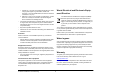
5.1 General instructions Any specific requirements for each system component are provided later in this chapter. Cable entry Equipment location Ensure the unit is mounted in a location which allows proper routing and connection of cables: When deciding on the location of system components, consider the following: • Minimum bend radius of 100 mm (3.94 in). • Use cable supports to prevent stress on connectors.
5.2 Remember GPM400 Processor module Where constraints on the installation prevent any of the above recommendations: • Always allow the maximum separation possible between different items of electrical equipment. • This will provide the best conditions for EMC performance for the installation. Suppression ferrites Raymarine cables may be fitted with suppression ferrites. These are important for correct EMC performance.
5.3 Mounting and environment The following conditions apply: • Do NOT install near sources of heat or vibration (e.g. engine). • The unit is NOT designed for use in a sealed enclosure. Access to the unit is required, e.g. for chart updates. • Must be mounted on a vertical surface. Sides and top must be level. • Mounting surface must be firm, secure and capable of supporting the weight of the unit. • Install below decks in a dry area.
Wired operation - flush mounted Dimensions Mounting arrangement 98 mm (3.85 in) G-Series keyboard 59.8 mm (2.35 in) minimum clearance 35 mm (1.38 in) Sun cover 46 mm (1.81 in) Keyboard Panel seal (adhesive side up) 297 mm (11.69 in) D10226-1 SeaTalk NG cable Mounting and environment • The keyboard is suitable for mounting both above and below decks. It is waterproof to CFR-46 standard. • Use the cutting template provided with the keyboard.
Cables • 1. Install charge point. Minimum bend radius of 100 mm (3.94 in). Note: Remove protective cover from each side of gasket See also Ensure you record your keyboard details on the schematic diagram. See Appendix B - Nav Station schematic. Ensure flat edge is located to left side for correct orientation Wireless upgrade kit Allows wireless operation of the keyboard. Cut 25 mm diameter hole Mounting and environment • The should be within sight of G-series monitors.
3. Fit the battery, taking care to avoid contamination of the cover seal. D10162-1 2. Fit splash cover.
Wireless basestation 4. Fit the rear cover. D10189-1 Required for wireless operation of the keyboard. 117 mm (4.61 in) 5. For charging and wired operation use the cable provided Note: The keyboard should be charged for 6 hours before use. 66 mm (2.6 in) G-Series Installation & Commissioning 64 36 mm (1.