Raymarine Limited Pathfinder Radar scanners FCC ID: PJ5MTX9-S3 Owner's Handbook Note 1: This Draft Owner's Handbook also covers the 2kW Radome Scanner (PJ5MTX2-S3), the 4kW Radome Scanner (PJ5MTX4-S3), the 4kW Open Array Scanner (PJ5MTX5-S3). Note 2: The information within the handbook is complete and up-to-date, except that the EC Declarations of Conformity will be replaced with new versions after of the current CE application. Raymarine Limited. Registered in England. Company No.
Pathfinder Radar Scanners Owner’s Handbook Document number: 81154_6 Date: 11th March2002
Pathfinder Radar Scanners i Pathfinder Radar Scanners Owners Handbook January 2002 Intended Use The scanner units detailed in this handbook form part of navigational radar systems intended for light marine use. These radar systems are only an aid to navigation. WARNING: The 4D radome scanner connected to an SL70, SL70 PLUS or SL70RC PLUS 7" LCD display unit DOES NOT conform to the EU directive 95/5/EC, therefore such a system cannot be installed on a vessel within the EU .
ii Pathfinder Radar Scanners Board Statement on Restrictions on Human Exposure to Static and Time Varying Electromagnetic Fields and Radiation, Doc NRPB, No. 5 (1993). 3. Navigation Aid. This radar unit is only an aid to navigation. Its accuracy can be affected by many factors, including equipment failure or defects, environmental conditions, and improper handling or use. It is the user’s responsibility to exercise common prudence and navigational judgements.
Pathfinder Radar Scanners iii Preface This handbook describes the following Raymarine Pathfinder radar scanners: 2D 4D 5S 7S 9S 11S 18" 24" 48" 72" 48" 72" 2 kW Radome Scanner 4 kW Radome Scanner 4 kW Open Array Scanner 4 kW Open Array Scanner 10 kW Open Array Scanner 10 kW Open Array Scanner These scanner units may be connected to any HSB/hsb2 display unit. In addition, the 2D radome scanner unit may be connected to an SL70, SL70 PLUS or SL70RC PLUS 7" LCD display.
iv Pathfinder Radar Scanners Note: If a scanner unit is not connected the version number is only displayed for 10 seconds. Where, necessary Software Upgrade Kits are available from your dealer, distributor or from Raymarine. We recommend that where a repeater display is fitted, both the repeater and the master display are upgraded. Warranty To register your Pathfinder Radar Scanner ownership, please take a few minutes to fill out the warranty registration card found at the end of this handbook.
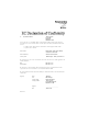
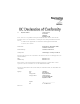
Certificate No. RT016 We Raymarine Limited Anchorage Park Portsmouth Hampshire England P03 5TD declare, under our sole responsibility, that the products identified in this declaration, and to which this declaration relates, are in conformity with the essential requirements of European Parliament and Council Directive: 1999/5/EC on radio equipment and telecommunication terminal equipment and the mutual recognition of their conformity.
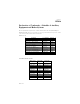
Certificate No. RT016 Declaration of Conformity – Schedule of Ancillary Equipment and Radar Systems The following Raymarine Display Units are combined with the Raymarine 2D – 2kW (8-Pulse Width), 18" Radome Scanner Unit (transceiver) listed on Sheet 1 to form the operational radar systems given below.
Certificate No. RT014 We Raymarine Limited Anchorage Park Portsmouth Hampshire England P03 5TD declare, under our sole responsibility, that the products identified in this declaration, and to which this declaration relates, are in conformity with the essential requirements of European Parliament and Council Directive: 1999/5/EC on radio equipment and telecommunication terminal equipment and the mutual recognition of their conformity.
Certificate No. RT014 Declaration of Conformity – Schedule of Ancillary Equipment and Radar Systems The following Raymarine Display Units are combined with the Raymarine 4D – 4kW (8-Pulse Width), 24" Radome Scanner Unit (transceiver) listed on Sheet 1 to form the operational radar systems given below.
Certificate No. RT011 We Raymarine Limited Anchorage Park Portsmouth Hampshire England P03 5TD declare, under our sole responsibility, that the products identified in this declaration, and to which this declaration relates, are in conformity with the essential requirements of European Parliament and Council Directive: 1999/5/EC on radio equipment and telecommunication terminal equipment and the mutual recognition of their conformity.
RT011 Declaration of Conformity – Schedule of Ancillary Equipment and Radar Systems The following Raymarine Display Units are combined with the Raymarine or Raytheon 4kW, Open Array Scanner Unit (transceiver) listed on Sheet 1 to form the operational radar systems given below.
Certificate No. RT012 We Raymarine Limited Anchorage Park Portsmouth Hampshire England P03 5TD declare, under our sole responsibility, that the products identified in this declaration, and to which this declaration relates, are in conformity with the essential requirements of European Parliament and Council Directive: 1999/5/EC on radio equipment and telecommunication terminal equipment and the mutual recognition of their conformity.
RT012 Declaration of Conformity – Schedule of Ancillary Equipment and Radar Systems The following Raymarine Display Units are combined with the Raymarine or Raytheon 10kW, Open Array Scanner Unit (transceiver) listed on Sheet 1 to form the operational radar systems given below.
xiii Contents Preface iii Warranty............................................................................... iv EMC Conformance ............................................................. iv Chapter 1: Overview ...............................................................................1 1.1 Introduction ....................................................................... 1 EMC installation guidelines ............................................. 2 1.
xiv Pathfinder Radar Scanners Appendix A: Specification ......................................................................45 2D 18" Radome Scanner Unit ........................................ 45 4D 24" Radome Scanner Unit ........................................ 47 5S and 9S 48" Open Array Scanner Unit ........................ 49 7S and 11S 72" Open Array Scanner Unit ......................
Chapter 1: Overview 1 Chapter 1: Overview 1.1 Introduction This handbook provides instructions to assist you in the installation and set up of the following radar scanners: 2D 4D 5S 7S 9S 11S 18" 2 kW Radome Scanner 24" 4 kW Radome Scanner 48" 4 kW Open Array Scanner 72" 4 kW Open Array Scanner 48" 10 kW Open Array Scanner 72" 10 kW Open Array Scanner These scanner units may be connected to any HSB/hsb2 display unit.
2 Pathfinder Radar Scanners CAUTION: Do not use an open array scanner with an SL70, SL70 PLUS or SL70RC PLUS 7" LCD display unit. Failure to observe this may result in permanent damage to these display units. The 10 kW open array scanner requires 24 V or higher; it will not operate on 12 V systems. This handbook is divided into three chapters as follows: Chapter One provides an overview of the scanner installation.
Chapter 1: Overview • • • 3 In the case of SSB radios, the distance should be increased to 2 m (7 ft). • More than 2 m (7 ft) from the path of a radar beam. A radar beam can normally be assumed to spread 20 degrees above and below the radiating element. The equipment is supplied from a separate battery from that used for engine start. Voltage drops below 10 V (20 V for 10 kW open array scanners) in the power supply to our products, and starter motor transients, can cause the equipment to reset.
4 Pathfinder Radar Scanners 1.2 Unpacking and inspecting the components Unpack your system carefully, to prevent damage to the equipment. It is good practice to save the carton and packing for future use, in case you need to return the unit for service. Check that you have all the correct system components. These depend on your system package, as detailed in the following tables. Table 1-1: Radome scanners Item Part No.
Chapter 1: Overview 5 1.3 Selecting the scanner unit site This section provides information that affects the possible locations of the scanner, and its position relative to the display unit and to the power supply. The dimensions of the each scanner unit are shown in the following diagrams.
Pathfinder Radar Scanners 227 mm (8.9 in) 6 Rear 302.5 mm (11.9 in) 151.25 mm (5.95 in) 116.5 mm (4.6 in) Rear 233 mm (9.2 in) 468 mm (18.4 in) dia. Weight: 6.5 kg (14.3 lbs) Compass safe distance: 1 m (33 in) 18" Radome Scanner D3224_4 227 mm (8.9 in) 141.5 mm (5.6 in) Rear 402 mm (15.8 in) 185.15 mm (7.3 in) 116.5 mm (4.6 in) Rear 233 mm (9.2 in) 599 mm (23.6 in) dia. Weight: 7.5 kg (16.5lbs) Compass Safe Distance: 1m (33") 141.5 mm (5.
Chapter 1: Overview 7 Open Array Scanners 48"- 1306 mm (51.4 in), 72"- 1928 mm (75.9 in) Centre of rotation 406 mm (16 in) Centre of rotation 100 mm (4 in) 427 mm (16.8 in) Weight Pedestal: 24 kg (53.0 lb) 48" Open Array: 6 kg (13.2 lb) 72" Open Array: 9.4 kg (20.7 lb) Compass Safe Distance: 1 m (33 in) Minimum clearance height 510 mm (20.1 in) 150 mm (6 in) 70 mm (2.75 in) 140 mm (5.5 in) 296 mm (11.65 in) Minimum clearance 630 mm (24.
8 Pathfinder Radar Scanners • • • • • • Access: The scanner unit site should be easily accessible to allow maintenance to be carried out safely. Magnetic compass: Mount the scanner unit at least 1 m away from a magnetic compass. Cable run: The maximum length of cable between the display unit and the scanner unit should not normally exceed 20 m (60 ft) for radome scanners, or 15 m (45 ft) for open array scanners.
Chapter 1: Overview 9 For open array scanners you should also consider the following points: • • • Mounting Platform: The platform must be mechanically secure and capable of supporting the mass and inertia of the open array scanner. The complete unit weighs: 48" scanner - 30 kg (66.2 lb); 72" scanner - 33.4 kg (73.7 lb). The site must be clear of ropes and moving rigging. Sufficient clearance must be allowed to fully open the open array pedestal for maintenance.
10 Pathfinder Radar Scanners Setting the radiation plane The scanner unit should be mounted so that the array rotates parallel to the waterline. The radar beam is approximately 25° wide in the vertical direction, providing good target detection during the vessel’s pitching and rolling. 12.5˚ 12.5˚ Waterline Ideal Radiation Plane D3223-2 Planing hull vessels, and some displacement hull vessels, adopt a higher bow angle when the vessel is at its cruising speed.
Chapter 1: Overview 11 1.4 Cable runs You need to consider the following before installing the system cables: • • • • • You need to fit the inter-unit cable and the power cable. All cables should be adequately clamped and protected from physical damage and exposure to heat - avoid running cables through bilges or doorways, or close to moving or hot objects. Acute bends must be avoided. Where a cable passes through an exposed bulkhead or deckhead, a watertight gland or swan neck tube should be used.
12 Pathfinder Radar Scanners If you are mounting the scanner on the mast of a sailboat, and will need to unstep the mast, you should install a suitable junction box inside the boat. On a radome scanner, the junction box should provide an 11- or 13way terminal strip, depending on the number of power cores in your cable, with a 10 A rating. Also, you should keep the length of the unscreened coaxial cores to less than 30 mm to maintain EMC conformance.
Chapter 1: Overview 13 Radome scanner cables Inter-unit cable The length of the supplied cable should be sufficient to complete the cable run required on most small vessels. For longer runs, additional or replacement cables are available, which have 4 power cores to minimize voltage drops over the longer cable run: these optional cables include 5 m and 10 m extension cables, and a 25 m replacement cable.
14 Pathfinder Radar Scanners Power cable The radome radar systems are intended for use on ships’ DC power systems operating in the 10.7 to 32 V DC range (that is, 12 V and 24 V systems, not 32 V systems). A 1.5 m (5 ft) power cable is supplied (with the display unit) for connecting the ship’s DC power to the radar scanner via the display unit. Refer to the HSB/hsb2 Series Display Owner’s Handbook for details on connecting this cable.
Chapter 1: Overview 15 Table 1-4: Max. Extension Power Cable Lengths (m), 12 V Systems 18" Radome Scanner Inter-Unit Cable(s) Power Cable Core (each core) mm2: 1.5 AWG: 16 2.0 15 2.5 14 4.0 11 6.0 10 10.0 7 10 m Light 5.0 7.0 9.0 14.0 20.0 35.0 10 m Light + 5 m ext 1.0 2.0 3.0 4.5 7.0 12.0 10 m Light + 10 m ext Do NOT extend the power cable 15 m Light 1.0 2.0 3.0 4.5 7.0 12.0 15 m Heavy 7.0 10.0 13.0 20.0 30.0 50.0 15 m Heavy + 5 m ext 5.0 7.0 10.0 15.0 25.0 40.
16 Pathfinder Radar Scanners Open array scanner cables Inter-unit cable Heavy duty cables are available in 15 m and 25 m lengths which should be sufficient to complete the cable run required on most small vessels. For longer runs, 5 m and 10 m extension cables are available, both have 4 power cores to minimize voltage drops over the cable run and incorporate in-line moulded plugs. The maximum inter-unit cable length is limited by the minimum supply voltage and the scanner type.
Chapter 1: Overview 17 24 V and 32 V Systems - 10kW scanners 10 kW open array scanners can use any combination of inter-unit cable up to a maximum length of 35 m. However, these systems use considerable power and installations should be planned to minimize all cable lengths. Refer to the tables on page 1-19, Max. Extension Power Cable Lengths (m) - 10 kW Scanner. Power cable The open array scanner systems are intended for use on ships’ DC power systems operating in the following ranges: 4 kW 10 kW 10.
18 Pathfinder Radar Scanners maximum power cable extensions are given in the table below. These figures relate to the total cable extension, from the end of the supplied 1.5 m power cable to the system battery terminals. Do not exceed these lengths as unreliable operation may result. Table 1-7: Max. Extension Power Cable Lengths (m), 12 V Systems 4 kW scanners Power Cable Core Size (each core) mm2: 4.0 AWG: 11 4 kW Scanners <3.0 6.0 10 8.0 8 10.0 7 4.5 6.0 7.
Chapter 1: Overview 19 Table 1-8: Max. Extension Power Cable Lengths (m), 24/32 V Systems 4 kW Scanners Power Cable Core Size (each core) mm2: 2.0 AWG: 14 4 kW Scanners 8.0 4.0 11 6.0 10 8.0 8 10.0 7 16.0 24 32 35 Table 1-9: Max. Extension Power Cable Lengths (m), 24 V Systems 10 kW Scanners Inter-Unit Cable(s) Power Cable Core (each core) mm2: 1.5 AWG: 16 2.0 15 2.5 14 4.0 11 5 m Heavy 12.0 16.0 20.0 32.0 10 m Heavy 10.5 14.0 18.0 28.0 15 m Heavy 9.0 12.0 16.0 24.
20 Pathfinder Radar Scanners
Chapter 2: Installing the Scanner 21 Chapter 2: Installing the Scanner 2.1 Radome scanner Securing the radome scanner to the mounting surface CAUTION: The drain tube must always be used, but may be shortened if necessary 1. Using the paper template supplied with the scanner mounting kit, mark the flat mounting surface with the mounting holes and drain tube hole, and drill the holes as indicated on the template.
22 Pathfinder Radar Scanners Scanner base Bitumen washer Mounting bracket or mounting surface Greased mounting bolt D3995-3 You may need to use longer M8 mounting bolts to secure the scanner if you have used shims to lower the radar beam. Connecting the radome scanner inter-unit cable CAUTION: Before wiring the scanner unit, make sure that the inter-unit cable is not connected and power is not applied to the display unit.
Chapter 2: Installing the Scanner 23 Inner cover (24" only) D4006-4 4. Remove the drain tube from inside the base of the scanner, and insert it into the drain hole as shown in the following diagram. Pull the tube gently from outside the scanner so that it clips into place.
24 Pathfinder Radar Scanners 5. Referring to the following illustration, remove the securing nut (1) from the watertight gland (2) and grommet (3), where the inter-unit cable (4) will enter the base. 9 White wire 12 8 5 11 6 7 10 12 11 1 2 3 4 4 10 D3230-5 1 Securing nut 2 Gland 3 Grommet 4 Inter-unit cable 5 Eight-way plug 6 Eight-way socket 7 Power cores (2 or 4) 8 Terminal clamp 9 Screwdriver 10 Earthing clamp 11 Top clamp 12 Clamp screws 6.
Chapter 2: Installing the Scanner 25 9. Connect the red “+”and black “-” power cores (7). If you have a 10 m or light 15 m inter-unit cable, there is one pair of cores. Connect the red cable lead to one of the terminal sockets marked “+”, and the black cable lead to one of the sockets marked “-”. If you have a heavy 15 m inter-unit cable, there are two pairs of cores.
26 Pathfinder Radar Scanners 2.2 Open array scanner Installation of the open array scanner should only be undertaken by a competent installer. If you have any difficulty with the installation, please contact your local Raymarine dealer or distributor. The open array scanner is supplied in two sections; the pedestal unit and the antenna. The pedestal unit is secured from below the mounting platform. The open array is then secured to the pedestal. Full details for mounting the scanner are given below.
Chapter 2: Installing the Scanner 27 Securing the pedestal to the mounting platform 1. Using the paper template supplied with the scanner mounting kit, mark the flat mounting surface with the holes and drill as indicated on the template. Refer to Section 1.2 when selecting the scanner unit site. 2. Stick the four self-adhesive bitumen washers over the mounting holes. 3. Ensure the lifting eyes are securely fitted to the top of the pedestal, and the yellow protective cap is in place.
28 Pathfinder Radar Scanners Pedestal Lifting eye IMPORTANT Bitumen washer, MUST be sticky side down on mounting platform Mounting platform 32 mm max. M10 stud length = 52 mm plus platform depth M10 plain washer M10 spring washer M10 nut D4573-4 Connecting the open array scanner inter-unit cable CAUTION: Before wiring the scanner unit check that it is securely mounted to the platform, then make sure that the inter-unit cable is not connected and power is not applied to the display unit.
Chapter 2: Installing the Scanner 29 4. Slide the cable through the gland nut, washer and grommet, then into the base. Carefully remove the heat shrink shroud, ensuring that you do not damage the cable. 5. Ensure the exposed braid is positioned in the p-clip to provide an earth, then clamp securely into position. Secure the cable at the entrance to pedestal base using the plastic cable clamp. Hand tighten the cable gland nut. . D4575-3 6.
30 Pathfinder Radar Scanners 1. Preparation of Wires 1. Remove the protective sleeve to a length of 535 mm ± 10 mm. 2. Using wire cutters, carefully remove the earthing braid to a length of 500 mm ± 10 mm. 3. Prepare co-axial wire as shown. 500 mm ± 10 mm 5-6 mm strip length Black power wires Red power wires Exposed braid Data wires (6 off) 35 mm See Note A Coaxial signal 25 mm See Note B 500 mm ± 10 Coaxial screen 10 mm mm 5-6 mm strip length Notes A.
Chapter 2: Installing the Scanner 31 and the black cable leads to the terminal socket marked “-”, with one lead in each socket. The terminal clamps are operated using a screwdriver as shown in the inset diagram. Signal connector Grey Purple Blue Green Yellow Orange Coaxial Screen (Black) Coaxial Inner (White) Power connector D4576-2 9. Using the tie-wrap fitting on the pedestal lid, secure the cable. 10. Check the seal in the pedestal lid is correctly seated.
32 Pathfinder Radar Scanners Fitting the open array to the pedestal CAUTION: The pedestal unit has a cap fitted over the open array mounting shaft to protect the protuding co-axial pin. This cap must be left in place until the open array is fitted to the pedestal. 1. Remove the cap from the open array shaft. Retain the cap, it will be required if the open array is removed from the pedestal. 2. Grease the four securing studs with Denso paste (supplied).
Chapter 2: Installing the Scanner 33 2.3 System connections DC power connection Power is supplied to the scanner via the display unit; the power cable is supplied with the display unit, refer to your display unit Owner’s Handbook for details on connecting power. However, you should be aware of the following. The DC system should be either: • • Negative grounded, with the negative battery terminal connected to the ship’s ground. Floating, with neither battery terminal connected to the ship’s ground.
34 Pathfinder Radar Scanners CAUTION: If you do not have a thermal circuit breaker or fuse in your power circuit, e.g. fitted to the DC distribution panel, you MUST fit an in-line breaker or fuse to the positive (red) lead of the power cable. Table 2-1: Isolator Switch/Thermal Breaker/Fuse Values Vessels Supply 12 V* 24/32 V** Device Open Array Systems 4 kW 10 kW Radome Systems Isolator Switch min.
Chapter 2: Installing the Scanner 35 Front view of Display Cable Connector 8 7 1 2 5 3 4 8 6 7 11 9 13 10 12 Display Video Video RTN 1 2 4 Battery --ve 5 Data I/O + 6 Tx Trigger -- 7 8 Battery +ve 9 Data I/O -- 10 *Battery +ve 11 Azimuth + Azimuth -- 6 5 4 3 2 1 Not fitted on Open Array Scanners (refer to Section 2.
36 Pathfinder Radar Scanners Display unit connection CAUTION: Do not use an open array scanner with an SL70, SL70 PLUS or SL70RC PLUS 7" LCD display unit. Failure to observe this may result in permanent damage to the display unit. 10 kW open array scanners cannot be directly connected to 12 V systems. The rear of the Pathfinder display includes the following connection sockets: • • Scanner connection Power/NMEA Input DC power connection, two NMEA 0183 inputs and one RF ground (screen) connection.
Chapter 3: Post Installation Checks and Maintenance 37 Chapter 3: Post Installation Checks and Maintenance Once you have installed your radar scanner and display unit, and made all the connections, you need to check your installation. You can then set up the radar system, align the scanner and check the display timing. In addition, for a 72" open array scanner you need to set the antenna size to ensure the scanner rests in the correct position when rotation stops.
38 Pathfinder Radar Scanners which the unit should enter Standby mode. If necessary, adjust the lighting and contrast. If required, change the default language settings. Checking transmission WARNING: The radar scanner transmits electromagnetic energy. Ensure that the scanner has been installed according to the recommendations given in Chapter 1, and that all personnel are clear of the scanner, before switching to transmit mode.
Chapter 3: Post Installation Checks and Maintenance 39 3.2 Maintenance Warnings The display unit and scanner unit contain high voltage. Adjustments require specialized service procedures and tools only available to qualified service technicians - there are no user serviceable parts or adjustments and the operator should not attempt to service the equipment. The operator should not remove the rear cover of the display or any internal covers in the scanner.
40 Pathfinder Radar Scanners • • enable you to ensure minimum interaction between different items of equipment, i.e. ensure optimum Electromagnetic Compatibility (EMC). Always report any EMC-related problem to your nearest Raymarine dealer. We use such information to improve our quality standards. In some installations, it may not be possible to prevent the equipment from being affected by external influences.
Chapter 3: Post Installation Checks and Maintenance 41 Technical Support: Please visit out website at: www.raymarine.com/recreational/support where you will find a Questions & Answers database, service information and e-mail access to the Technical Support department.
42 Pathfinder Radar Scanners For Product Repair and Service In the unlikely event your Raymarine unit should develop a problem, please contact your authorized Raymarine dealer for assistance. The dealer is best equipped to handle your service requirements and can offer time saving help in getting the equipment back into normal operation.
Chapter 3: Post Installation Checks and Maintenance 43 Accessories and Parts Raymarine accessory items and parts are available through your authorized Raymarine dealer. Please refer to the lists of component part numbers and optional accessories in the Installation chapter of this manual, and have the Raymarine part number ready when speaking with your dealer.
44 Pathfinder Radar Scanners
Appendix A: Specification 45 Appendix A:Specification 2D 18" Radome Scanner Unit General Approvals CE - conforms to FCC - conforms to 1999/5/EC, EN60945 Part 80 (47CFR) and Part 2 (47CFR) Dimensions Φ468 x 227 mm (18.4 x 8.9 in) Weight 6.5 kg (14.3 lbs) Input Voltage 8.
46 Pathfinder Radar Scanners Antenna Antenna Type Patch array Beam Width (nominal) 5.2° horizontal, 25° vertical Polarization Horizontal Antenna Side lobes Less than -22 dB Rotation Rate 24 rpm (nominal) Receiver IF Frequency 60 MHz (nominal) Receiver Characteristic Semi-log Receiver Noise Figure Less than 5 dB (including Low Noise Converter/Limiter & IF Receiver) Receiver Bandwidth 12/3/0.7/0.
Appendix A: Specification 47 4D 24" Radome Scanner Unit General Approvals CE - conforms to FCC - conforms to 1995/5/EC, EN60945 Part 80 (47CFR) and Part 2 (47CFR) Dimensions Φ599 x 227 mm (23.6 x 8.9 in) Weight 7.5 kg (16.5 lbs) Input Voltage 8.
48 Pathfinder Radar Scanners Antenna Antenna Type Patch array Beam Width (nominal) 3.9° horizontal, 25° vertical Polarization Horizontal Antenna Side lobes Less than -22dB Rotation Rate 24 rpm (nominal) Receiver IF Frequency 60 MHz (nominal) Receiver Characteristic Semi-log Receiver Noise Figure Less than 5 dB (including Low Noise Converter/Limiter & IF Receiver) Receiver Bandwidth 12/3/0.7/0.
Appendix A: Specification 49 5S and 9S 48" Open Array Scanner Unit General Approvals CE - conforms to FCC - conforms to 1995/5/EC, EN60945 Part 80 (47CFR) and Part 2 (47CFR) Dimensions Pedestal: Array: 427 x 296 x 406 mm (16.8 x 10.5 x 16 in) 1306 mm (51.4 in) length Weight Pedestal: Array: 24 kg (53.0 lb) 6 kg (13.
50 Pathfinder Radar Scanners 9S Transmitter - 10 kW Input Voltage 16 - 44 V DC (from display unit) Power Consumption 11 W Standby 80 W Typical operation in light winds 95 W Max. operation in 50 Kt winds 140 W Max.
Appendix A: Specification 51 Receiver IF Frequency 60 MHz (nominal) Receiver Characteristic Semi-log Receiver Noise Figure Less than 5 dB (including Low Noise Converter/Limiter & IF Receiver) Receiver Bandwidth 12/3/0.7/0.5 MHz Note: If the scanner is bought for use with an existing display, contact your dealer/service agent for the latest display software to ensure you can use all the open array scanner features.
52 Pathfinder Radar Scanners 7S and 11S 72" Open Array Scanner Unit General Approvals CE - conforms to FCC - conforms to 1995/5/EC, EN60945 Part 80 (47CFR) and Part 2 (47CFR) Dimensions Pedestal: Array: 427 x 296 x 406 mm (16.8 x 10.5 x 16 in) 1918 mm (75.5 in) length Weight Pedestal: Array: 24 kg (53.0 lb) 9.4 kg (20.
Appendix A: Specification 53 11S Transmitter - 10 kW Input Voltage 20 - 44 V DC (from display unit) Power Consumption 11 W Standby 80 W Typical operation in light winds 117 W Max. operation in 50 Kt winds 179 W Max.
54 Pathfinder Radar Scanners Receiver IF Frequency 60 MHz (nominal) Receiver Characteristic Semi-log Receiver Noise Figure Less than 5 dB (including Low Noise Converter/Limiter & IF Receiver) Receiver Bandwidth 12/3/0.7/0.5 MHz Note: If the scanner is bought for use with an existing display, contact your dealer/service agent for the latest display software to ensure you can use all the open array scanner features.
Index Index A Alignment Bearing 38 Position of 72" Open Array Scanner 38 B Bearing Alignment 38 C Cable Runs 11 Cables Extension 4 Open Array 16, 18, 19 Radome 13, 15, 17 Inter-unit 4, 11, 12 Open Array 16, 29 Radome 13, 22 Part Numbers 4 Power 11 Open Array 17 Radome 14 Rejoining 11 Connections Display Unit 36 Open Array Scanner 28 Power 33, 36 Radome Scanner 22 Scanner 34 System 33 D Display Timing Adjustment 38 Display Unit Connections 36 E Electromagnetic Energy i, 38 EMC iv Conformance iv Installation
ii R Radar System Grounding 33 Typical System Diagram 1 Radome Scanner 18" iii, 1, 45 24" iii, 1, 47 Connections 22 Mounting 21 Rejoining Cables 11 Routine Checks 39 S Safety - and Servicing 39 Electromagnetic Energy i High Voltage i Navigation Aid ii Scanner i Connections 34 Location 5 Mounting on Power Boats 9 on Sailboats 9 Scanner - See also Open Array Scanner, Radome Scanner i Servicing and Safety 39 Set Up 37 Specification 18" Radome Scanner 45 24" Radome Scanner 47 48" Open Array Scanner 49 72" Open
Limited Warranty Certificate Raymarine warrants each new Light Marine/Dealer Distributor Product to be of good materials and workmanship, and will repair or exchange any parts proven to be defective in material and workmanship under normal use for a period of 2 years/24 months from date of sale to end user, except as provided below. Defects will be corrected by Raymarine or an authorized Raymarine dealer.
Factory Service Centers United States of America UK, Europe, Middle East, Far East Raymarine Inc 22 Cotton Road, Unit D Nashua, NH 03063-4219, USA Raymarine Ltd Anchorage Park, Portsmouth PO3 5TD, England Telephone: +1 603 881 5200 Fax: +1 603 864 4756 www.raymarine.com Telephone: +44 (0)23 9269 3611 Fax: +44 (0)23 9269 4642 www.raymarine.com Sales & Order Services Telephone: +1 800 539 5539 Ext. 2333 or +1 603 881 5200 Ext.