Evolution EV-1 and ACU INSTALLATION INSTRUCTIONS English (en-US) Date: 01-2017 Document number: 87180-4 © 2017 Raymarine UK Limited
Trademark and patents notice Raymarine, Tacktick, Clear Pulse, Truzoom, HSB, SeaTalk, SeaTalkhs, SeaTalkng, Micronet, Raytech, Gear Up, Marine Shield, Seahawk, Autohelm, Automagic, and Visionality are registered or claimed trademarks of Raymarine Belgium. FLIR, DownVision, SideVision, Dragonfly, Quantum, Instalert, Infrared Everywhere, and The World’s Sixth Sense are registered or claimed trademarks of FLIR Systems, Inc.
Contents Chapter 1 Important information............. 7 Water ingress ............................................ 7 Disclaimer.................................................. 8 Suppression ferrites .................................. 8 Connections to other equipment ............... 8 Declaration of conformity........................... 8 Product disposal........................................ 8 Warranty registration ................................. 8 IMO and SOLAS........................................
Chapter 6 System checks and ACU-150 ................................................. 32 troubleshooting ...................................... 49 Drive (motor) connection — ACU-100, SeaTalkng® connection — ACU-100, ACU-150 ................................................. 32 Rudder reference connection.................. 33 4.4 ACU-200, ACU-300, ACU-400 connections ............................................. 34 Connections overview — ACU-200 .................................................
Chapter 1: Important information Warning: Autopilot system Installation As correct performance of the vessel’s steering is critical for safety, we STRONGLY RECOMMEND that an Authorized Raymarine Service Representative fits this product. You will only receive full warranty benefits if you can show that an Authorized Raymarine Service Representative has installed and commissioned this product.
Disclaimer Warranty registration Raymarine does not warrant that this product is error-free or that it is compatible with products manufactured by any person or entity other than Raymarine. To register your Raymarine product ownership, please visit www.raymarine.com and register online.
Chapter 2: Document and product information Chapter contents • 2.1 Handbook information on page 10 • 2.
2.1 Handbook information Description This handbook describes installation of the Evolution autopilot system. The handbook includes information to help you: • plan your autopilot system and ensure you have all the necessary equipment, • install and connect the EV-1 and ACU (if applicable) as part of the autopilot system, • obtain support if required. This and other Raymarine product documentation is available to download in PDF format from www.raymarine.com.
Description Part number 2.2 Product overview Hydraulic Linear Drive Installation instructions Installation and commissioning instructions for the following Hydraulic Linear Drives: E12207, E12208, M81202, M81203 81177 Evolution is a system of electronic components that give you autopilot control of your vessel’s steering system.
Required additional components Multiple data sources (MDS) overview To complete your autopilot system, you will need the following components and data sources in addition to the Evolution components. Essential: When a system includes multiple instances of a data source the preferred data source is selected automatically. The systems preferred source may not be your preferred source, or if you are experiencing a data conflict you can manually select your preferred data source.
Chapter 3: Planning the installation Chapter contents • 3.1 Installation checklist on page 14 • 3.2 Parts supplied on page 14 • 3.3 Software updates on page 15 • 3.4 Compatible autopilot controllers on page 16 • 3.5 Compatible drive units on page 17 • 3.6 System examples on page 19 • 3.7 Warnings and cautions on page 21 • 3.8 Selecting a location on page 21 • 3.
3.1 Installation checklist 3.2 Parts supplied Installation includes the following activities: Parts supplied — EV-1 and EV-2 Installation Task 1 Plan your system. 2 Obtain all required equipment and tools. 3 Site all equipment. 4 Route all cables. 5 Drill cable and mounting holes. 6 Make all connections into equipment. 7 Secure all equipment in place. 8 Power on and test the system. Schematic diagram A schematic diagram is an essential part of planning any installation.
Parts supplied — ACU-200, ACU-300, ACU-400 3.3 Software updates The software running on the product can be updated. • Raymarine periodically releases software updates to improve product performance and add new features. • The software on many products can be updated using a connected and compatible multifunction display (MFD). • Refer to www.raymarine.com/software/ for the latest software updates and the software update procedure for your specific product. Item Description Quantity 1 ACU unit.
3.4 Compatible autopilot controllers A SeaTalkng® autopilot controller is required to operate your autopilot system. SeaTalk autopilot controller can be used when connected via a SeaTalk to SeaTalkng® converter, but may have limited functionality. More than 1 autopilot controller can be used to control your autopilot system.
3.5 Compatible drive units The drive unit interfaces with the vessel’s steering system. The type of drive required depends on the type of vessel and capacity of the associated steering system. Raymarine autopilot systems accommodate hydraulic, mechanical and power assisted stern drive systems.
Drive category Available types Universal stern drive For use with inboard / outboard (I/O) vessels with cable power-assisted steering. Suitable ACU * Max output ACU-200 15 A ACU-200 15 A Wheel drive — Power (Sport Drive) Designed for smaller power vessels featuring a steering system that can be driven directly from the helm position.
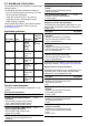
3.6 System examples Example: Evolution recommended system ACU-100, ACU-150 Example: Evolution minimum system ACU-100, ACU-150 1. 12 V dc power supply (providing power to SeaTalkng®) 2. EV-1 sensor 3. Autopilot controller 4. SeaTalkng® backbone 5. SeaTalkng® 5–way block 6. Drive unit (example) 7. 12 V dc power supply (providing power to the ACU) 8. ACU 1. 12 V dc power supply (providing power to SeaTalkng®) 2. EV-1 3. Wind transducer (only required for Sailing vessels) 4. Speed data source: a.
Example: Evolution minimum system ACU-200, ACU-300, ACU-400 Example: Evolution recommended system ACU-200, ACU-300, ACU-400 1. Autopilot controller 2. EV-1 sensor 3. SeaTalkng® backbone 4. 12 V / 24 V dc power supply (providing power to the ACU and SeaTalkng® backbone) 5. ACU 6. SeaTalkng® 5–way block 7. Drive unit (example) 1. Autopilot controller 2. EV-1 3. Wind transducer (only required for Sailing vessels) 4. Speed data source: a. Speed transducer (STW), or b. GNSS Receiver (SOG) 5. iTC-5 6.
3.7 Warnings and cautions Important: Before proceeding, ensure that you have read and understood the warnings and cautions provided in the Chapter 1 Important information section of this document. 3.8 Selecting a location Warning: Potential ignition source This product is NOT approved for use in hazardous/flammable atmospheres. Do NOT install in a hazardous/flammable atmosphere (such as in an engine room or near fuel tanks).
between equipment and minimize the effect such interference could have on the performance of your system Correct installation is required to ensure that EMC performance is not compromised. Note: In areas of extreme EMC interference, some slight interference may be noticed on the product.Where this occurs the product and the source of the interference should be separated by a greater distance.
3.
Chapter 4: Cables and connections Chapter contents • 4.1 General cabling guidance on page 26 • 4.2 EV connections on page 26 • 4.3 ACU-100, ACU-150 connections on page 29 • 4.4 ACU-200, ACU-300, ACU-400 connections on page 34 • 4.
4.1 General cabling guidance 4.2 EV connections Cable types and length Connections overview — EV-1 and EV-2 It is important to use cables of the appropriate type and length • Unless otherwise stated use only standard cables of the correct type, supplied by Raymarine. • Ensure that any non-Raymarine cables are of the correct quality and gauge. For example, longer power cable runs may require larger wire gauges to minimize voltage drop along the run.
Power connection — EV-1 Note: The power for the EV-1 unit is provided by the SeaTalkng® backbone. The suitable fuse rating for the thermal breaker is dependent on the number of devices you are connecting. If in doubt consult an authorized Raymarine dealer. • The EV-1 unit must be connected to a spur connection on the SeaTalkng® backbone. • SeaTalkng® requires ONE 12 V dc power source.
• If you need to extend the length of the power cable, ensure you use suitably rated cable and that sufficient power (12 V dc) is available at the SeaTalkng® backbone’s power connection. Important: Be aware that the suitable fuse rating for the thermal breaker or fuse is dependent on the number of devices you are connecting.
4.3 ACU-100, ACU-150 connections Warning: Positive ground systems Do not connect this unit to a system which has positive grounding. Connections overview — ACU-100, ACU-150 Fuses and circuit protection There are 3 levels of power protection in the autopilot system. The drive (motor) and associated cables are initially protected by the current sensing and stall condition detection within the ACU hardware and software.
ACU-150 15 A Important: ACU-200 20 A ACU-300 15 A ACU-400 40 A When planning and wiring, take into consideration other products in your system, some of which (e.g. sonar modules) may place large power demand peaks on the vessel’s electrical system. Grounding — Dedicated drain wire required This product includes a dedicated drain conductor (screen) for connection to a vessel's RF ground point. It is important that an effective RF ground is connected to the unit.
• Alternatively, the unit’s power connection may be connected to a suitable breaker or switch on the vessel's power distribution panel, or factory-fitted power distribution point. • The distribution point should be fed from the vessel’s primary power source by 8AWG (8.36mm2) cable. • Ideally, all equipment should be wired to individual suitably-rated thermal breakers or fuses, with appropriate circuit protection.
Drive Supply voltage Note: Cable size The connection colors for the motor cables may be different depending on the motor type. 12 V 0–5 m (0–16.4 ft) 24 V 0–5 m (0–16.4 ft) 6 5–7 m (16.4–23 ft) 10 mm2 (8 AWG) 0–7 m (0–23 ft) 2.5 mm2 (14 AWG) 7–10 m (23–32.8 ft) 4 mm2 (12 AWG) 0–7 m (0–23 ft) 2.5 mm2 (14 AWG) 7–10 m (23–32.8 ft) 4 mm2 (12 AWG) SeaTalkng® connection — ACU-100, ACU-150 0–7 m (0–23 ft) 2.
Rudder reference connection A rudder reference sensor unit can be connected to the ACU to provide rudder angle information to the autopilot system. The connection of a rudder reference unit is highly recommended, to help ensure optimum autopilot performance. Note: A rudder reference sensor is not included with all autopilot products or system packs. Consult the Raymarine website or your local dealer for a full list of the components included with your autopilot system.
4.4 ACU-200, ACU-300, ACU-400 connections Connections overview — ACU-400 Connections overview — ACU-200 1. SeaTalkng® connection 2. Digital input / output connection 3. Sleep switch connection 1. SeaTalkng® connection 4. Power connection 2. Sleep switch connection 5. Motor (drive) connection 3. Power connection 6. RF ground connection (drain conductor) 4. Motor (drive) connection 7. Rudder reference connection 5. RF ground connection (drain conductor) 6. Rudder reference connection 8.
Warning: Positive ground systems ACU-200 20 A ACU-300 15 A Do not connect this unit to a system which has positive grounding. ACU-400 40 A Fuses and circuit protection There are 3 levels of power protection in the autopilot system. The drive (motor) and associated cables are initially protected by the current sensing and stall condition detection within the ACU hardware and software. A second level of protection is provided to these parts and the ACU components by the unit's main power fuse.
Important: When planning and wiring, take into consideration other products in your system, some of which (e.g. sonar modules) may place large power demand peaks on the vessel’s electrical system. Note: The information provided below is for guidance only, to help protect your product. It covers common vessel power arrangements, but does NOT cover every scenario.
3 Circuit breaker 4 Fuse Drive Where possible, connect individual items of equipment to individual circuit breakers. Where this is not possible, use individual in-line fuses to provide the necessary protection. Supply voltage The amount of electrical current available to the autopilot system components will be impacted by the length and gauge of the cables used to connect all the components.
2. Motor (not all compatible variants are shown in the illustration above) Clutch voltage switch Clutch connection colors Color Description A Red Clutch Positive (+) connection B Blue Clutch Negative (–) connection Motor power output ACU–200 ACU-400 15 A (maximum continuous output) 30 A (maximum continuous output) If the drive has a separate clutch connection, you must ensure that the clutch voltage switch on the ACU is set correctly to suit the connected drive.
Bypass valve connection and voltage switch Some drives feature an electrically-operated bypass valve to minimize the effect on the steering when the autopilot is in standby. If the drive has a separate bypass valve, connect it to the Bypass connection on the ACU, ensuring that the voltage selection switch is set correctly to 12 V / 24 V as appropriate. Important: To avoid potential damage to equipment, ensure voltage selector switch is set to the correct setting.
SeaTalkng® power switch (ACU-200, ACU-300, ACU-400 only) The ACU-200, ACU-300, ACU-400 can provide power to the SeaTalkng® backbone. This will provide power to certain equipment connected to the backbone (e.g. SeaTalkng® autopilot control head and instrument displays). Set the SeaTalkng® power switch on the connector panel to the appropriate position: • ON — The ACU-200, ACU-300, ACU-400 will supply power to the SeaTalkng® backbone. the rudder is centered.
4.5 SeaTalk® pilot controller connection The SeaTalk® to SeaTalkng® converter can be used to enable control of SeaTalkng® autopilots using legacy SeaTalk® pilot controllers. Other SeaTalk® devices can be connected to the SeaTalkng® backbone in the same way. 1. SeaTalkng® MFD (MFDs require a separate power supply.) 2. SeaTalk® to SeaTalkng® adaptor cable (A22164) 3. SeaTalk® pilot controller (powered from the SeaTalkng® backbone.) 4. SeaTalkng® autopilot 5. SeaTalkng® 12 V dc power supply connection 6.
Chapter 5: Installation Chapter contents • 5.1 EV-1 Installation on page 44 • 5.2 ACU Installation on page 46 • 5.
5.1 EV-1 Installation Surface mounting the EV-1 The supplied Deck mounting kit is used to surface mount the unit. Ensure that the chosen location meets the product’s location requirements, see 3.8 Selecting a location for details. Important: The unit must be mounted with the LED ‘arrow’ in parallel alignment with the longitudinal axis (centerline) of the vessel and be pointing towards the vessel’s bow. 7.
2. Place the small sealing ring in the groove located on the bottom of the Mounting tray. 3. Secure the tray to the bracket using 3 of the supplied screws, in the positions indicated in the illustration above. 4. Place the large sealing ring into the groove on the upper side of the Mounting tray. 5. Pull the SeaTalkng® cable through the canter of the bracket and tray. Plug in the cable connector on the underside of the unit and secure by rotating the locking collar clockwise 2 clicks. 6.
5.2 ACU Installation connectors from the sockets, as shown in the following illustration: Mounting the ACU-100, ACU-150 Ensure that the chosen location meets the product’s location requirements, see 3.8 Selecting a location for details. Important: The installation must only be performed with the vessel either on a hard standing, or tied-up alongside a pontoon or berth. 1. Using an appropriate screwdriver, undo the screws located on the top cover and remove the top cover from the ACU. 4.
Mounting the ACU-200, ACU-300, ACU-400 Important: The installation must only be performed with the vessel either on a hard standing, or tied-up alongside a pontoon or berth. 1. Mount the ACU in an appropriate location and secure with the screws supplied. 5.3 Drive unit installation For instructions on how to install the drive unit for your autopilot system, refer to the dedicated Installation instructions supplied with the drive unit.
Chapter 6: System checks and troubleshooting Chapter contents • 6.1 Post-installation checks on page 50 • 6.2 Autopilot system setup on page 50 • 6.3 Alarms on page 51 • 6.4 LED indications — EV-1 on page 54 • 6.
6.1 Post-installation checks These checks should be carried out after installation, and prior to the commissioning of the autopilot system. 1. Switch on power to the autopilot system and associated equipment. • ACU (for EV-1 systems only) • Autopilot controller • SeaTalkng® backbone (if this has its own power supply) 2. Check that the autopilot controller powers up. If the display is blank press and hold the Power button for 2 seconds. 3.
6.3 Alarms Alarms are raised by the autopilot system to alert you to mechanical and electrical conditions requiring your attention. The Evolution components transmit alarm alerts on the SeaTalkng® network for display on autopilot controllers and MFDs, along with an audible alert. The Evolution components stop raising an alarm when the alarm condition ceases or the alarm is acknowledged on the autopilot controller or MFD. If the alarm is safety-critical it will be raised again after a timed delay.
Alarm Message Possible causes Solution NO RUDDER REFERENCE No rudder reference unit is detected, or the rudder reference unit has turned outside its operational range (50 degrees). If a rudder reference unit is installed, check the wiring. Inspect the unit for possible damage. STALL DETECTED Motor speed dropped too low for given course change or motor stalling. This can be caused by a faulty drive unit or steering fault. Alternatively, the steering hard-over time may be too slow.
Alarm Message Possible causes Solution JOYSTICK FAULT A fault has occurred with the joystick. This alarm applies only to autopilot systems that include a joystick controller. Check the connections to, and operation of the joystick. NO IPS (NO DRIVE DETECTED) Loss of communications between the EV-1 and ACU, or EV-2 and drive interface unit. Check all physical data connections between these devices, as appropriate.
6.4 LED indications — EV-1 LED color LED code Status Action required Solid green Normal operation. • None (normal power up takes <1 minute.) Long flash green on (x1), long flash off. Cycle repeats after 2 seconds. Unit is initializing; no pilot or compass functions currently available. • None (normal power up takes <1 minute.) Short flash red on No SeaTalkng® (x2), long flash off. connection. Cycle repeats after 4 seconds. • Ensure network is powered.
6.5 LED indications — ACU LED color LED code Solid green Status Action required Normal operation. • None (normal power up takes <1 minute.) Short flash red on No SeaTalkng® (x2), long flash off. connection. Cycle repeats after 4 seconds. • Ensure network is powered. • Ensure network cable and connections are secure and free from damage. • If problem persists contact Raymarine technical support. Short flash red on SeaTalkng® (x7), long flash off.
Chapter 7: Maintenance Chapter contents • 7.1 Service and maintenance on page 58 • 7.2 Routine equipment checks on page 58 • 7.
7.1 Service and maintenance 7.2 Routine equipment checks This product contains no user serviceable components. Please refer all maintenance and repair to authorized Raymarine dealers. Unauthorized repair may affect your warranty. Raymarine strongly recommends that you complete a number of routine checks to ensure the correct and reliable operation of your equipment. Complete the following checks on a regular basis: • Examine all cables for signs of damage or wear and tear.
7.3 Product cleaning Best cleaning practices. When cleaning products: • Lightly rinse or flush with clean, cool fresh water. • If your product has a display screen, do NOT wipe the screen with a dry cloth, as this could scratch the screen coating. • Do NOT use: abrasive, acidic, ammonia, solvent of chemical based cleaning products. • Do NOT use a jet wash.
Chapter 8: Technical support Chapter contents • 8.1 Raymarine product support and servicing on page 62 • 8.
8.1 Raymarine product support and servicing Raymarine provides a comprehensive product support service, as well as warranty, service, and repairs. You can access these services through the Raymarine website, telephone, and e-mail. Product information If you need to request service or support, please have the following information to hand: Region Telephone E-mail Australia and New Zealand +61 2 8977 0300 aus.support@raymarine.com (Raymarine subsidiary) France +33 (0)1 46 49 72 30 support.
8.2 Learning resources Raymarine has produced a range of learning resources to help you get the most out of your products. Video tutorials Raymarine official channel on YouTube: • http://www.youtube.com/user/RaymarineInc Video Gallery: • http://www.raymarine.co.uk/view/?id=2679 Product Support videos: • http://www.raymarine.co.uk/view/?id=4952 Note: • Viewing the videos requires a device with an Internet connection. • Some videos are only available in English.
Chapter 9: Technical specification Chapter contents • 9.1 Technical specification — EV-1 and EV-2 on page 66 • 9.2 Technical specification — ACU-100, ACU-150 on page 67 • 9.
9.1 Technical specification — EV-1 and EV-2 Nominal supply voltage 12 V (powered by SeaTalkng® system). Operating voltage range 10.8 V to 15.6 V dc. Power consumption (taken from SeaTalkng® system) 30 mA. SeaTalkng® LEN (Load Equivalency Number) 1 Sensors • 3-axis digital accelerometer. • 3-axis digital compass. • 3-axis gyro digital angular rate sensor. Data Connections • SeaTalkng®. • NMEA 2000 DeviceNet (EV-2 only; port not used on EV-1 unit).
9.2 Technical specification — ACU-100, ACU-150 ACU-100 ACU-150 Drive current output • Maximum continuous 7 A at supply voltage. • Maximum continuous 12 A at supply voltage. Drive clutch output No clutch connection. No clutch connection. Connections • Rudder reference sensor. • Rudder reference sensor. • Power. • Power. • Drive motor. • Drive motor. • Ground. • Ground. Nominal supply voltage 12 V 12 V Operating voltage range 10.8 V to 15.6 V dc 10.8 V to 15.
9.3 Technical specification — ACU-200, ACU-300, ACU-400 ACU-200 ACU-300 ACU-400 Drive current output • Maximum continuous 15 A at supply voltage. • Maximum continuous 5 A at supply voltage. • Maximum continuous 30 A at supply voltage. Drive clutch output Up to 2.0 A continuous, selectable between 12 / 24 V No clutch connection. • Up to 4 A continuous at 12 V on 12 V systems. • Up to 4 A continuous at 24 V on 24 V systems. • Up to 4 A continuous at 12 V on 24 V systems.
Chapter 10: Spares and accessories Chapter contents • 10.1 Spare parts on page 70 • 10.2 Evolution SeaTalkng cable kit on page 70 • 10.
10.2 Evolution SeaTalkng cable kit 10.1 Spare parts Item Part number SeaTalkng cable kit R70160 Notes Consists of: • SeaTalkng power cable 0.4 m (1.3 ft) (quantity: 1). • SeaTalkng backbone cable 5 m (16.4 ft) (quantity: 1). • SeaTalkng spur cable 0.4 m (1.3 ft) (quantity: 1). A SeaTalkng cable kit is available for Evolution components. This cable kit provides the cables required to make all the SeaTalkng connections for some typical Evolution systems.
10.3 SeaTalkng® cables and accessories SeaTalkng cables and accessories for use with compatible products. Description Part No SeaTalkng starter kit T70134 Notes Includes: • 1 x 5 Way connector (A06064) • 2 x Backbone terminator (A06031) • 1 x 3 m (9.8ft) spur cable (A06040) • 1 x Power cable (A06049) SeaTalkng Backbone Kit A25062 Includes: • 2 x 5m (16.4ft) Backbone cable (A06036) • 1 x 20m (65.
Appendix A NMEA 2000 sentences (PGNs) — EV-1 and EV-2 EV-1 and EV-2 support the following NMEA 2000 sentences.
Message number Message description Transmit Receive • Active Leg Origin Waypoint ID • Active Waypoint ID • Destination Waypoint Latitude • Destination Waypoint Longitude • Waypoint closing velocity 129285 Active Waypoint data ● 130306 Wind data ● 74
Appendix B NMEA 2000 sentences (PGNs) — ACU The ACU supports the following NMEA 2000 sentences.
Index A ACU (Actuator Control Unit) ...................................11 AHRS (Attitude Heading Reference Sensor) ..........11 Alarms ................................................................... 51 Autopilot controller documentation ........................ 10 Autopilot controllers, SeaTalk® ............................. 16 Autopilot controllers, SeaTalkng® ......................... 16 Autopilot set-up...................................................... 50 B Backbone length, SeaTalkng® ..........
N Network length, SeaTalkng®, See Backbone length, SeaTalkng® Technical support................................................... 62 Thermal breaker rating, SeaTalkng®..................... 27 U O Upgrading, See Software updates Optional system components ................................ 12 V P Post-installation ..................................................... 50 Power cable length .......................................... 31, 37 Power cable size .............................................
www.raymarine.com Raymarine UK Limited, Marine House, Cartwright Drive, Fareham, PO15 5RJ. United Kingdom.