Distributed by Any reference to Raytheon or RTN in this manual should be interpreted as Raymarine. The names Raytheon and RTN are owned by the Raytheon Company.
ST40 Compass Instrument Owner’s Handbook Document number: 81161_2 Date: 1st May 2001 161_2cov.
Copyright © Raymarine Limited 2001 161_2cov.
i Preface Important information WARNING Although your ST40 instrument is designed to give accurate and reliable performance, it should serve only as an aid to navigation and should never lead to the erosion of good seamanship. Always maintain a permanent watch and be aware of situations as they develop. EMC conformance All Raymarine equipment and accessories are designed to the best industry standards for use in the leisure marine environment.
ii 161_2pre.
iii Preface Contents Important information .......................................................... i WARNING ......................................................................... i EMC conformance ............................................................. i Handbook information ....................................................... i Preface ..................................................................................... v Parts supplied ....................................................
iv ST40 Compass Instrument Owner’s Handbook Chapter 3: Installation ......................................................... 11 3.1 Planning your installation ......................................... 11 EMC installation guidelines ...................................... 11 Suppression Ferrites ........................................... 12 Connections to Other Equipment ......................... 12 Tools required ........................................................... 12 Site requirements ...........
v Preface Preface Thank you for purchasing a Raymarine product. We are sure your ST40 instrument will give you many years of trouble-free operation. This instrument is designed to provide reliable performance, even under the most demanding conditions. D48 161_2pre.
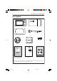
vi ST40 Compass Instrument Owner’s Handbook Parts supplied COMPASS ST40 ST40 Compass instrument Instrument Cover 1 m (3 ft) power cable Gasket Fixing stud Thumb nut Fluxgate compass transducer Clamping bracket ST40 Compass Instrument - quick reference guide Normal operation SWITCH ON ST40 Compass Instrument Owner's Handbook Worldwide Distributors Locked heading Compass heading Course computer sets auto lock Course computer sets auto lock Auto locked heading Alarm on/off Times out to the
1 Chapter 1: Operation Chapter 1: Operation 1.1 Introduction Your ST40 Compass instrument: • Provides true and magnetic bearing information. • Enables a locked bearing to be defined either manually, or automatically by a course computer. In this mode, the instrument shows the deviations from the locked bearing and the direction to steer to achieve the locked bearing.
2 ST40 Compass Instrument Owner’s Handbook NORMAL OPERATION Switch on Increase locked heading Locked heading Compass heading STEER ST40 ST40 COMPASS COMPASS Decrease locked heading Autopilot sets auto lock Auto locked heading ST40 COMPASS To maintain course on a locked heading, steer your vessel so that the minimum number of segments are displayed, ideally so that the flashing segment is at the 12 o'clock position.
3 Chapter 1: Operation Backlighting and contrast adjustment Hold down for 1 second to enter Adjust Backlight mode for 2 seconds to move through Adjust Backlight mode and enter Adjust Contrast mode ADJUST BACKLIGHTING During normal operation, press for 1 second The current backlighting level is displayed.
4 ST40 Compass Instrument Owner’s Handbook 1.3 Screen descriptions Compass heading screen Either M (magnetic) or T (true) Cardinal points (North flashing) Current heading ST40 COMPASS Press to set the current compass bearing as the locked heading D4774-2 Locked heading screen Locked heading Either magnetic (M) or true (T) Course divergence from locked heading STEER Current heading ST40 COMPASS Direction to steer to return to locked heading.
5 Chapter 1: Operation 1.4 Alarms Off course active alarm Heading error STEER Current heading ST40 COMPASS D4773-2 Enabling/disabling alarm You can enable or disable the off course alarm function (i.e. switch it on or off ) by selecting the Set off course alarm threshold screen (see Normal operation) and holding down the key for 3 seconds (toggle action).
6 161_2c01.
7 Chapter 2: Maintenance and Fault Finding Chapter 2: Maintenance and Fault Finding 2.1 Maintenance Servicing and safety • Raymarine equipment should be serviced only by authorised Raymarine service technicians. They will ensure that service procedures and replacement parts used will not affect performance. There are no user-serviceable parts in any Raymarine product. • Some products generate high voltages, so never handle the cables/ connectors when power is being supplied to the equipment.
8 ST40 Compass Instrument Owner’s Handbook Instrument Certain atmospheric conditions may cause a small amount of condensation to form on the instrument window. This will not harm the instrument and will clear after the instrument has been switched on for a short period. Periodically clean your ST40 instrument with a soft damp cloth. Do NOT use chemical or abrasive materials to clean the instrument.
9 Chapter 2: Maintenance and Fault Finding Action Low battery Recharge your vessel’s battery as soon as possible D4755-2 Action Check fuse/circuit breaker. Display blank Check power supply. ST40 COMPASS D4777-2 No heading information Check SeaTalk cabling and connector security. Action Check the condition of the fluxgate compass transducer cable and the security of the connections. ST40 COMPASS D4778-2 SeaTalk information not being transferred between instruments 161_2c02.
10 ST40 Compass Instrument Owner’s Handbook A group of SeaTalk instruments not working Action ST40 WIND ST40 WIND ST40 WIND Check the security of SeaTalk connectors between functioning and non-functioning instruments. D4758-2 Assistance If you are unable to rectify any problem, please contact your local Raymarine Dealer for assistance. 161_2c02.
11 Chapter 3: Installation Chapter 3: Installation This chapter describes how to install the ST40 Compass instrument, and associated Fluxgate Compass transducer. 3.1 Planning your installation Determine the best positions for both transducer and instrument, such that the EMC installation guidelines and the Site requirements (below) are satisfied. EMC installation guidelines All Raymarine equipment and accessories are designed to the best industry standards for use in the leisure marine environment.
12 ST40 Compass Instrument Owner’s Handbook • The equipment is supplied from a different battery from that used for engine start. Voltage drops below 10 V in the power supply to our products, and starter motor transients, can cause the equipment to reset. This will not damage the equipment, but may cause the loss of some information and may change the operating mode. • Raymarine specified cables are used at all times.
13 Chapter 3: Installation 57 mm (2.25 in) D4643-3 Note: If you intend fitting a nonstandard transducer, extra tools may be required. Site requirements Fluxgate Compass transducer The Fluxgate Compass transducer should be positioned as near as possible to the pitch/roll centre of the vessel, as shown in the shaded areas below. 0.3L to 0.5L L X 0.3L to 0.5L L Fluxgate Compass transducer siting 161_2c03.
14 ST40 Compass Instrument Owner’s Handbook The Fluxgate Compass transducer must also be sited: • At least 0.8 m (2 ft 6 in) away from the vessel's steering compass to avoid deviation in both compasses. • On a bulkhead below deck. Note: On steel vessels the Fluxgate Compass transducer can be mounted above deck. When mounted above deck, performance may be impaired due to increased motion. • To allow reasonable access for installation and servicing.
15 Chapter 3: Installation 3.2 Procedures Adapt these procedures as appropriate, to suit your individual requirement. CAUTION: Where it is necessary to cut holes (e.g. for cable routing and instrument mounting), ensure that these will not cause a hazard by weakening critical parts of the vessel’s structure. If in doubt, seek advice from a reputable boat builder.
16 ST40 Compass Instrument Owner’s Handbook 76 mm (3 in) 76 mm (3 in) D729-6 If you are not sure of the magnetic suitability of the chosen location, carry out a survey of the site as follows: 1. Temporarily fix a simple hand bearing compass at the intended location. 2. Swing the vessel through 360° while at the same time observing differences between the hand bearing compass and the vessel's main steering compass. 3.
17 Chapter 3: Installation Connections to the instrument You can connect your instrument: • Directly to the compass transducer as a stand-alone master instrument. When connected in this manner, the instrument must be connected to a suitable power source using the 1 m (3 ft) power cable provided. • As part of a SeaTalk system either as a repeater or, with a transducer also connected as a system master. To connect to SeaTalk, you will need an additional SeaTalk Interconnection Kit (Part No. E25028).
18 ST40 Compass Instrument Owner’s Handbook Stand-alone connections CAUTION Ensure that the power supply for each stand-alone ST40 instrument is protected by a 3 A fuse or circuit breaker. 3 A circuit breaker Red +ve Note: A 3 A fuse can be used in place of the circuit breaker, if preferred. Uninsulated wire (screen) -ve 12 V dc supply (e.g.battery) Power cable Red Green Screen Yellow Blue _ Cable from Fluxgate Compass transducer Connections to a stand-alone instrument 161_2c03.
19 Chapter 3: Installation SeaTalk connections CAUTION When instruments are connected to SeaTalk, ensure that the power supply for the SeaTalk 12 V line is protected by a 5 A fuse or circuit breaker. Note: A 5 A fuse can be used in place of the circuit breaker, if preferred. 5 A circuit breaker Red (+ve) 12 V dc supply (e.g.
20 ST40 Compass Instrument Owner’s Handbook 2 Cut hole 57 mm (2.25 in) cutter D4760-1 3 Peel protective sheets from gasket D4770-1 4 Stick gasket to rear of instrument D4761-1 161_2c03.
21 Chapter 3: Installation 5 Screw stud into instrument D4819-1 6 Feed cables through clamping bracket, connect cables then secure instrument with bracket and thumb nut D5030-1 Desktop Mounting Bracket An optional Desktop Mounting Bracket (Part No. E25024) enables you to mount your ST40 instrument in locations where other forms of mounting are impractical. 161_2c03.
22 ST40 Compass Instrument Owner’s Handbook D4646-1 To bracket mount your ST40 instrument, do so in accordance with the Instruction Sheet, which is included with the Desktop Mounting Bracket. 3.3 Calibration requirement Once installation is complete and before you use your instrument, carry out the calibration procedures detailed in Chapter 4, Calibration. 161_2c03.
23 Chapter 4: Calibration Chapter 4: Calibration 4.1 Introduction The procedures in this Chapter must be carried out before the equipment is used operationally, to optimise the performance of the instrument with the vessel. Calibration information is presented in flow chart form. The flow charts show the various calibration screens and key presses necessary to carry out calibration. All key presses are momentary unless otherwise stated.
24 ST40 Compass Instrument Owner’s Handbook USER CALIBRATION During normal operation hold down and for approximately 2 seconds Set heading alignment Entry screen ST40 COMPASS Increase CAL Flashing ST40 segment = North COMPASS Decrease Deviation 15 (fast) Set compass heading CAL response ST40 Note: If there is no key activity when the Entry screen is displayed, calibration will time out to normal operation after 5 seconds, CAL ST40 COMPASS 1 (slow) COMPASS When linearisation successful (
25 Chapter 4: Calibration 4.3 Intermediate calibration Intermediate calibration enables you to: • Check the instrument software version. • Check the instrument status - either master (shown as RPTR NO) or repeater (shown as RPTR YES). You cannot make any adjustments in Intermediate calibration. Follow the procedure in the Intermediate calibration flow diagram.
26 ST40 Compass Instrument Owner’s Handbook DEALER CALIBRATION During normal operation hold down and for approximately 12 seconds Entry screen Note: If there is no key activity when the Entry screen is displayed, calibration will time out to normal operation after 5 seconds, ST40 COMPASS Calibration access CAL ST40 COMPASS If If Boat show mode Factory defaults CAL CAL ST40 ST40 Return to normal operation with factory defaults applied COMPASS COMPASS CAUTION: Do NOT switch the Boat Show mo
Instrument Specification 27 Instrument Specification Supply voltage: 10 V to 16 V dc. Current consumption (12 V supply): 20 mA typical. 60 mA with maximum backlighting. Operating temperature: 0°C to +70°C. Interfaces: SeaTalk. Overall dimensions: 126 mm x 70 mm x 38 mm (5.00 inches x 2.80 inches x 1.55 inches). Boss diameter: 55 mm (2.20 inches). Heading range: 0 to 359°. Off course alarm: 2° to 30° (port or starboard). Approvals: CE - conforms to 161_2spe.p65 89/336/EC(EMC), EN60945.
28 161_2spe.
Glossary 29 Glossary EMC Electromagnetic Compatibility. M Metres. MOB Man overboard. Response The rate at which an instrument responds to changes in heading. Values are from 1 (slow response) to 15 (fast response). SeaTalk SeaTalk is a proprietary Raymarine system which links different compatible products, to provide a single, integrated navigational system.
30 161_2glo.
31 Index Index A F Alarms indications 5 man overboard 5 off course 5, 27 silencing 1 Aligning heading 24 Factory defaults 25 Fault finding 8 assistance 10 blank display 9 low battery 9 no heading information 9 SeaTalk problems 9 Fluxgate Compass transducer checking suitability of site 16 fitting 15–16 fitting as part of a system 15 installing 15 site requirements 13 with stand alone instrument 15 B Backlighting 3 Boat show mode 25 C Calibration 23–26 Dealer 25–26 Intermediate 25 setting user access
32 ST40 Compass Instrument Owner’s Handbook L T Linearising transducer 24 Locked heading 2 auto 2 response 24 screen 4 Low battery indication 9 Transducer linearising U User calibration 23–24 V M Maintenance 7–8 Man overboard alarm 24–25 Variation 24 Voltage 27 5 O Off course alarm enabling 2 enabling/disabling 5 indications 5 range 27 setting 2 Operating procedures 1–5 Operating temperature 27 P Panel lighting 3 Parts supplied vi S Servicing and safety 7 Setting backlighting 3 compass heading
161_2tem.p65 33 01/05/01, 16:52 ST40 Instrument Template Cut out shaded area only TOP D4800-1 Cut out hole 57 mm (2.
161_2tem.
84064_8.fm Page 1 Monday, April 9, 2001 4:42 PM Limited Warranty Certificate Raymarine warrants each new Light Marine/Dealer Distributor Product to be of good materials and workmanship, and will repair or exchange any parts proven to be defective in material and workmanship under normal use for a period of 2 years/24 months from date of sale to end user, except as provided below. Defects will be corrected by Raymarine or an authorized Raymarine dealer.
84064_8.fm Page 2 Monday, April 9, 2001 4:42 PM Factory Service Centers United States of America UK, Europe, Middle East, Far East Raymarine Inc 22 Cotton Road, Unit D Nashua, NH 03063-4219, USA Raymarine Ltd Anchorage Park, Portsmouth PO3 5TD, England Telephone: +1 603 881 5200 Fax: +1 603 864 4756 www.raymarine.com Telephone: +44 (0)23 9269 3611 Fax: +44 (0)23 9269 4642 www.raymarine.com Sales & Order Services Telephone: +1 800 539 5539 Ext. 2333 or +1 603 881 5200 Ext.