Distributed by Any reference to Raytheon or RTN in this manual should be interpreted as Raymarine. The names Raytheon and RTN are owned by the Raytheon Company.
NAV398GPS/IL>RAI\l GPSlLORAN OPERATION MANUAL i
Table of Contents Page SECTION 1 INTRODUCTION 1 .O General 1.1 About This Manual l-l l-l SECTION 2 INSTALLATION 2.0 General 2.1 Unpacking and Inspection 2.1.1 Equipment Supplied 2-l 2-l 2-l 2.2 Display Installation 2.2.1 Choosing a Location 2.2.2 Mounting the NAV Unit 2.2.3 Flush Mounting 2-2 2-2 2-3 2-3 2.3 Electrical Connections 2.3.1 Power Input 2.3.2 Sensor Connections 2.3.3 Interface to External Navaids 2.3.4 Ground Connection 2-4 2-5 2-5 2-6 2-7 SECTION 3 OPERATION 3.1 General 3.
3.5 Main Display Modes 3.5.1 Position Display Mode 3.5.2 Customizing Display Modes 3.5.3 Navigation Display Mode 3.5.4 CD1 Display Mode 3.5.5 Plot Display Mode 3.5.6 Simulator Mode 3.5.7 Display Mode Operations 3.5.7.1 Saving Events 3.5.7.2 GOT0 Destinations 3-8 3-8 3-11 3-l 1 3-12 3-13 3-16 3-16 3-16 3-17 3.6 Entering Waypoints 3.6.1 General Waypoint Information 3.6.2 Waypoint Directory 3.6.3 Naming Waypoints 3.6.4..Storing Waypoints 3.6.4.1 Entry by L/L 3.6.4.2 Entry by TDs 3.6.4.
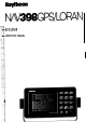
SECTION 1 INTRODUCTION 1 .O General Congratulations on selecting Raytheons’ NAV 398 for Loran-C/GPS navigation aboard your vessel. We are sure you will enjoy using this ultra modern, full function, and compact navigation system. The NAV 398, with its’ large STN LCD display, excellant graphics, on-sceen prompts, and oversized soft silicon keys, provide simple operations to guide you through the various navigation functions.
In the event that you are using a Loran-C Navigator for the first time, please refer to the Raynav 508/508~ Loran-C Sensor instruction manual for basic loran information. The Introduction section of the 508 manual includes a listing of common Loran C Terminology used with loran. If your NAV398 is using the RAYSTAR 108 GPS Sensor, the Raystar 108 instruction manual includes a general description of the GPS system which may also be helpful.
S E C T I O N 2 INSTALLATION 2.0 General Although your NAV 398 is designed to the highest levels of quality and performance, it can best attain those standards only when it has been properly installed. This section provides the user with practical guidelines to assist in the planning and the installation of the NAV 398 aboard your vessel. 2.1 Unpacking and Inspection Use care when unpacking the unit from its shipping carton to prevent damage to the contents.
2.2 Display Installation 2.2.1 Choosing a Location When choosing the location to mount the NAV Display unit, please consider the following criteria for the site: l The best location to provide ease of operation and viewing of the unit. l The best location to provide protection from the elements of the environment.
2.2.2 Mounting the NAV Unit Use the following steps for yoke mounting of the NAV Unit: 1. Loosen the yoke knobs on each side of the unit. and remove the mounting yoke bracket. 2. Position the bracket to the mounting surface and mark the holes for the mounting screws. 3. Mount the bracket with the screws supplied. 4. Slide the unit back into the yoke and secure in the desired viewing position by tightening the yoke knobs. IN THE YOKE BRACKET 4 HOLES .25” I , 8.07”? 2.2.
required. When using the Trim Ring Kit, add 3/4” to the width and height clearance dimensions. CAUTION Make sure there are no hidden electrical wires or other items behind the desired location before proceeding. Check to see that free access for mounting and cabling is available. 2.Using the dimensions for the cutout hole shown, draw the pattern for the cutout hole on the console. 3. Drill two l/2” pilot holes inside the cutout guide area at diagonal corners. 4.
2.3.1 Power Input The NAV 398 is intended for use on vessels with 12 VDC power systems and can operate as long as the DC supply is maintained between 10 and 16 volts. The DC power system can be “negative” ground or have both positive and negative supply lines “floating” above ground.
provide ship’s L/L position data on their own without other input requirements. In a typical installation, the 6-pin GPS sensor connector is plugged directly into the jack labeled “GPS” on the rear of the cabinet. The 5 Pin plug of the Loran-C sensor is connected to the jack labeled “LORAN”. ‘SZ zz If you are using the Raystar 108 GPS sensor together with the DGPS Beacon Receiver, the “Y” cable lead marked “Display” plugs into the GPS jack. 2.3.
accepting position data in the NMEA format. Please refer to the Raystar 108 or Raynav 508/508A instruction manuals for details on making this type of interconnection. Data Input One feature of the NAV398 is to transfer the waypoint and route memory contents of the internal memory to external computer files and to re-load the memory from the computer. Downloading of files occurs through the Data Output connections (Green and Yellow wires).
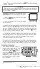
N 34v4. 714' w 118" 35.236' I 123'm DTG 11.7nm 093'm Sffi 10.9kt - I ! \ - NAV 1 3 N 34O14.714' w 118" 35.236' ) POS 2 b-l l ’ 0 N 34Ol4.714' w 118" 35.236' N 35%. 452 , w115v5.223 MAIN DISPLAY MODES - NAV 398 INSTALLATION 2-8 . _. _ . ..._._,_ ,. -. _I . ..“. ~. a- -.w.
SECTION3 OPERATION 3.1 General This chapter provides instructions for the operation of your new NAV 398 LCD NAVigator unit. We think you will find the operation of the NAV 398 to be easy and straightforward. The approach to take in becoming familiar with it’s operation is one of relaxed confidence. The unit is quite “user friendly” and relies on screen prompting to guide you through the operations and set-up menus.
The keyboard consists of 15 silicon rubber keys. Some of the keys carry dual labels such as(ormkeys and are normally used to enter the main operations of the NAV unit. The numeric operation of the key is used once vou have entered the main oueration. Notice that some keys such as 1-1 and/morJMENUJ have only one label and perform only one operation when depressed. When Menus are on screen, th$%%& IGoTo/7) and thdE[ keys are softkeys used to activate selections on the menus. .
3.3 Basic Operations Now that the NAV unit has been properly installed and the keypad layout has been described, we should be ready to begin learning the basic operations of the unit. So, let’s press the power key and get going! 3.3.1 Turning Unit On/ Off To turn the unit ON, press themlkey. To turn the unit OFF, press the /pwRp
I l.“,T.. 10 H -se NWV 9PB II II MRSON NAV398 L” ‘&WON 1.0 -4 ROM OK RAM OK SENSOR OK NOW TESTING II I 1 To SIONAL SYAYU.9 (IF NOT lMCNlN0) To FMlYlON DlSFiAY IF TRACK,,,O. The ID screen is then followed by a second screen which advises that the SELF TEST is in process, and a third screen prints the SELF TEST results . anytime by pressing the The Signal Status screen provides a readout or the progress made by the sensors in acquisition and tracking of the signals.
If the Differential Beacon Receiver is connected and tracking the beacon signal “DGPS” is indicated in the message window. The latitude/longitude readouts will include the differential corrections for greater accuracy. When the Loran-C mode is selected, the “LORAN” characters will be illuminated along in the message window of the display and the L/L position and ship’s course and speed data is then Loran-C derived.
The sensors always store the Lat/Lon position in memory. The next time you use the NAV unit, the only thing you’ll have to do is just turn it “ON”. In a few minutes your position will be displayed. 3.4.1 Estimated Latitude With the "ESTIMATED POSITION" screen displayed, enter the latitude of your position, using six digits. It is a good idea to enter your position to within one degree of latitude. When the numbers are correct. nress(. I ESTIMATED POSITION I 1 95. QQ' WQQQ' QQ.
one degree of longitude. For longitudes of less than 100 degrees, begin the entry with “0”. After you press the mjey, check to see that the direction symbol “W” is correctly indicated to the left of your longitude entry. If “E” is displayed, to change press the \r/wl softkey the symbol to fgW'T or vice versa. If the direction is correct, pres@CKJ. Example: 0,7,1,1,4,5,0, mJ=lfor W 71’ 14.50’ If you make any mistakes while entering your longitude, press the-1 key and retype the entry.
More information on the Status and signal tracking screens appears later in this chapter. 3.5 Main Display Modes The NAV 398 has FOUR Main Display modes used most often during normal navigation. They are the POS (Position), NAV (NAVigation), CD1 Graphic , and PLOT Tracking display modes. These modes can be selected directly by pressing: [ml for the POS mode displays I=[ for the NAV screens f o r t h e CD1 d i s p l a y s m[ )pLoT/FII for the Plot screens 3.5.
I I Along the bottom row, the sensor “in use” is indicated in the highlighted block. If the Raynav 508 is used, “LORAN” appears in the block. If the Raystar 108 is used, “GPS” appears together with the current GPS Fix mode type. If the Differential Beacon Receiver is connected and a beacon is received and differential corrections are included, “DGPS” will be indicated.
POS 4 The POS 4 screen brings up the coordinates of the destination waypoint to the screen so you can compare the numbers. TDs are shown here because matching the TD coordinates is an ideal way to return to a favorite wreck for fishing, TDs are stored in the waypoint memories any time you save a location as an Event or by direct entry of TDs as a waypoint location. TDs are not saved when Lat/Lons are entered as waypoints. 14096.2Irs 26160.4~s Note also, that the sensor mode in use here is the Loran-C.
Anytime you switch from the Display modes to other functions and return ‘to the same mode, the last selected screen reappears. However, when the power is turned OFF and then ON again, the last used POS screen is always selected. We’ve seen 5 different Position screens so far. There are also 4 Navigation screens and 4 CD1 screens. Having so many screens of information available sounds great, but there may be a few screens you will seldom use.
z3Yn iE3". IT.7 nm 8.9 kt Generally, the NAV screens are more useful once a waypoint has been entered into the units’ memories . Once a waypoint destination is selected, the NAVY display will feature large readouts of the destination Bearing (BRG)and Distance-to-go (DTG) to the waypoint combined with the Course and Speed readouts. . The readouts in the upper section of the display show the XTE,TTG, local time, and trip log distance.
the line and whether the vessel is closing, paralleling, or opening away from the line. A bit of the vessel track history appears behind the boat symbol. Up ahead, the waypoint destination is in view. If the destination is identified by a symbol or name, the first character will be blinking near the target area. Nearby waypoint symbols ( two closest to vessel) may be in view on the screen if they are within range.
The PLOT 2 screen re-arranges the BRG and DTG readouts and adds the vessels’ current position data to the screen. The L/L readout can be turned OFF in the PLOT DISPLAY menu for better viewing. Plot Scales The Plot size or scaling can be changed to show the navigation area of interest by pressing the softkeys indicated by thmorm{arrows. Plot scales available for the plot screen are 0.125, 0.25, 0.5, 1, 2, 5, 10, 20, 50, 100, or 200 NM.
.----.-u- Press the [TRACK INTERVALlso&ey until the desired memory interval is highlighted by the block. Now track recording will be ON. The NAV unit has Auto Start/Stop plotting built in. So, if you should stop along the way to fish, and forget to turn the track recording interval off, the tracker should automatically stop plotting until you’re moving again. All track points recorded will be “saved” in track memory until erased, or unless overwritten by new track data.
Press lCLEAR[twice to return to the last selected display mode. 3.5.6 Simulator Mode The NAV 398 includes a simulator mode which can show simulated readouts on the various screens. There I are dynamic simulated screens for both loran and GPS and can be used to demonstate navigation to waypoints and following route plans. PLOT MENU TRACK MENU + DlSPlAY MENU + To turn the simulator ON, be in Plot mode and press thelE\key . Press the ~SIMULATOR~ sofIkey to ON.
then go ahead and press thelENTER(key. The memory will be updated, and the screen returns back to the last POS, NAV, CDI, or PLOT display. One caution on saving Events. For maximum accuracy, it’s best to be sitting next to the desired location and let the readouts settle down for a few seconds before pressing themjkey. If you are flying by a buoy at high speed, the readouts will be displaying a position lagging behind the boat a short distance. The faster you are moving, the greater the lag error will be.
on track in the center. The is ON the track line. XTE value will be set to “0.00 nm” since the vessel Ideally, the helmsman sets the vessel’s heading with his steering compass or autopilot to the bearing shown for the waypoint destination and begins watching the CD1 scale at the top of the NAV display, the XTE digital value, or the active graphic CD1 screen.
3.6 Entering Waypoints 3.6.1 General Waypoint Information One of the key operations of the NAV 398 is to guide you to planned or pre-programmed waypoint destinations from your present position. Waypoints can be entered into your 398 unit by using one of the following four methods: l Storing au “Event” (instantly saves ship’s present position as you pass a buoy, enter a channel, or are sitting on top of a great fishing spot).
STORE WAYPOINT OPERATIONS (WPT I-m-J c-1 ENlERNEWWPT? -_------ * ENTER WPT NO. 0-w UsEmmiKEY FOR NEW ICONS OOTO WFT LIST 1 KEv*FHID 3 KEY=REv FRESS CIEAR TO EXIT & ND(T) ~W~b,pomlT tapll ----e-w- 2b USE~KEY FOR NEW ICONS de 1 KEv=FWO X* 3 KEY=REv CONllNUE t I t d IATtLONG zdX@QtOI PRESS ENTER TO IMR STOAE wNKnNT WPTloOZ smPEwPrm I Note: II press CLEAR key. onb# data to he last ENTER wed. @ - [SmRE &II. WAypolNl- 1 WPTnot N WC9 ENT TO ENTER UT W’ - t + ’ e-*-w.
/GOTO WAYPOINT LISA Press this softkey to see a directory of the waypoint memories. When the WAYPOINT LIST page appears, use the 1 (up) / 3 (down) numeric keys (one at a time) to scroll through the memory listings in either direction. When either key is held down, the scrolling operation speeds up so memories can be accessed more quickly.
any blank space in the typewriter box and then press the softkeys required to add the character. If you make a mistake, just position the a d x ABC GHI MN0 blinking cursor over the incorrect character o(Oe D E F J K L WR with the 3 (REV) key and re-type the car. rect character in its place. STU YZl 567 VWX 294 8 9 0 When the NAME is complete, press thei- key. If you want to bypass this page without naming the waypoint until later, just press thev[ key.
_._... , Enter the waypoint Longitude coordinates by typing the numeric value. Begin with a “0” if the Longitude is less than 100’. Press 1-1 when the value is correct anqn\again if the direction is displayed correctly. If the indicated direction is incorrect, press the softkey for “E” or “w”. Example: Press 0,8,2, 1, 0,2, S,Im(ENTER[ Long. = W 82’ 10.
3.6.4.3 Storing by Bearing/distance Occasionally, you may wish to enter a waypoint into memory by describing the waypoint’s position as a bearing and distance from your own current position. This is easily accomplished with your NAV unit. However, while describing a range or distance from your vessel should not be a problem, it is important to make sure your “bearing” information is in “magnetic” IF the magnetic variation is “ON”.
3.6.5.1 Selecting Waypoints To control the positioning of the list contents, the 1 (up) key lets you look at the listed waypoints at - the top of the list; the 3 (down) key lets you look at waypoints down the list. The waypoint # appearing in the highlighted block is the “selected” waypoint and is the waypoint that can be operated on if the [mJar m keys are pressed. ’ G N ? 42 m 65--- ’ 7 a~~Z&~i~{EOtT~ . W 71’ 16. 34 I 3.6.5.
On the WAYPOINT SF screen, confirm that the number shown under ERASE WAYPOMT is correct. Also verify that the Waypoint Protection feature for the selected waypoint is OFF. Press the 1 E RASE WAYPOINT~ soflkey. The waypoint will be erased. WARNING ! Make sure that the waypoint to be erased is NOT selected as your current destination. Only waypoints protected “manually” cannot be accidentally erased. C.
..T_” 3.7 Setting Alarms The NAV 398 has three operator programmable alarms that you can set to advise you when limits have been reached. The types of alarms available are: l ARRIVAL- Arrival at a waypoint. l ANCHOR - Exceeds Anchor drift limit. l OFF COURSE- Straying too far from track. Whenever an alarm is set and activated, the audible beeper will sound and the alarm characters will blink on-screen. You can set an Arrival alarm or Anchor alarm, but not both types together.
alarm is initially set to 0.10 nm from the factory to provide an arrival alert in the event that one is not set by the operator. 3.7.2 The Anchor Alarm The anchor alarm is intended to be used to monitor your vessel’s position while at anchor. If the vessel begins to drift beyond the entered distance of the anchor alarm, the alarm wiII sound off and notify the crew of the possible dragging of the anchor.
3.7.3 Off-Course Alarm The Off-Course alarm can be used to alert you when you are steering to a specific waypoint destination if your vessel strays too far away from your ./?‘O intended track line to the selected way- Cc .--**-* point. This is particularly useful if you &G@ N---d** are using an autopilot to monitor its effectiveness. To set the Off-Course alarm, press theplkey. Press the(OFF COURsEI softkey.
The arrival alarm is preset to 0. lnm and activates whenever you are within this area relative to the MOB. As always, press the -1 key to silence the audible alarm. To Cancel the MAN-Overboard function and return to the Position displaypress and hold the[MOB/8lkey for about 3 to 4 seconds until a second beep is heard and the MOB characters disappear from the screen. NOTE: The MOB location is not “Saved” to memory permanently and the location will be lost when the MOB mode is cancelled.
3.9.1 Making Route Plans. Press themlkey and the "ROUTE screen appears. Press thejm[softkey. MODE -'I When the lm[key is pressed, the MAKE ROUTE Selection screen appears to prompt you to choose a route number for your route plan. Choose any number from those listed on the screen and press(ENTER( MAKE ROUTE SELECT NOWE NUYBER Example: 4, -1, for route plan 4. m 67690 ! The display willchangeto the MAKE ROUTELEGS display and prompt you to enter your starting waypoint.
When you have completed the entry of all the waypoints for a particular route plan, just press thewqkey. The new route plan will be stored and the display will promptly return to the last used Display mode. 3.9.2 FollowRoute Plans Once a route plan has been made and saved into I/ memory, it can be recalled to Followed or to be Edited. Press the-key. The ROUTE MODE screen will appear. Press theI- softkey.
When-is pressed the route sequence mode, will be ON. The route number will be displayed in the left corner of the waypoint information bar on the POS, NAV, or CD1 screens and the first point of the route plan becomes your initial destination, unless you happen to already be at the first point of the route. While you are following the route plan you may press themlkey anytime to bypass the next point in the route plan.
Press theI=j key puts the screen into an Edit condition so you can INSERT or DELETE waypoints. Notice that two softkeys ILEG and m (insert) appear on the screen. To INSERT a Waypoint For example; to insert a new waypoint between waypoints #006 and #036, press(LEGI[ and them[arrow until you see the leg containing Fr 006/to 036. If this is where you would like to INSERT the new waypoint, Press the msoftkey Type the new waypoint number ( # 002) and pressF1 The new waypoint will now appear between 006,002,036.
function or setup that requires change. The paragraphs that follow will endeavor to provide simple guidelines for you. 7 MENU 1 SYSTEMSTATUSMENU ] wrfUNlTS ’ . DATAINWJT NW SETUPS * I . 4 NAV SENPE MENU 1 mur 0 YL(lNEllt r MANUAL vAnlAmll ) lb SIGNALSTATUS ) COURSi3BEAJlINQS mEscl.sAnmm ) - TO SJgnol Slcluc PoSmONCORR ) - -) MENU OPERATIONS mu AVERAGING 1 AVENAGING LORAN i I I ( mSmONCORR. LORAN1 N 00.00’ w 00.00’ I msssapumoQT r 1 GEODETICSVSTEM WaMl . 7; . dul.
3.10.2 Signal Status Pages The SIGNAL STATUS displays are used to show the conditions of signal acquisition and tracking of the attached sensors and thereby indicate the quality of the position fix. If the NAV unit is using both a loran and GPS sensor, the status of the sensor in use is always displayed. You may choose GPS or Loran operation while in the normal Display modes by pressing the k e y . vl 3.10.2.
As you may remember from reading the basic loran information in the R~~NAV 508 manual, the secondaries get their numbers by using the first digit of their normal time delay. On this display you actually see the TDs of all the loran signals, but the two “S” numbers highlighted in the reverse block characters at the left side are the stations being used to get your Lat./Long readout. So in the Status page example in the preceeding figure, the ” 1“) “4” line and the “6” lines are being received.
I’ STATION m 9960 B SELECTION I-l I 1 AUTO STATION @ mom NEWGRI? D TOGGLES TRW REGISTERED GRls 6 J Sl, S2 SELECTION ml I NEW Sl. S2? + B St12 PRESS ENTER TO RETURN GRI 3.10.2.3 Station Selection Mode If for some reason the SNR values or the Track Status of the SELECTED stations in the Automatic Station Select mode are poor and the loran will not lock-on, you can choose Manual Station mode and make station selections manually using the signals that are received in good quality.
Selection of Secondaries When pS1,S2?( softkey is pressed, the screen will change to the ” S 1, $2 Selection” screen. On this page the top line of large characters shows the received secondary stations from the selected GRI. To enter the two secondary stations for S 1 and $2 that you would prefer to use for your Lat/Lon calculations, Press thasoftkey for a NEW S 1 station and using the numeric keys, type the number of the desired station. Then pres$%%@ The softkey arrows will return.
In the title box, the fix type is displayed at the right end. Here, you will see either 3D or 2D characters. The 2D mode is a two-dimensional position fix mode that will not factor the calculated altitude (antenna height) into the L/L position solution. AUTO mode calculates altitude. Generally, the 2D mode works the best for marine navigation. The Status display also includes readouts of your estimated position, local date and time, and antenna height. There are two softkeys on the GPS Status screen.
Example: Press 4,2,0,5,0,0~~,~/, for N42’05.00’ Check the direction displayed to the left of the Latitude. Use thakey to change “S” to “N” or vice versa. Press-it0 save the Latitude. Estimated Longitude The prompt now moves to request your Longitude entry . Type in the correct longitude value. Add a “0” for Longitudes below 100 degrees. Pres!$Ml Example: Press 0,6,9,5,9,8,5,[~,~~, for W69’ 59.85’ Check the direction displayed to the left of the Longitude.
Local Time Entry When 1-1 is pressed to accept the Date entry, the display will prompt you to enter Local time. Enter the hour and minutes (+/- 15 minutes) using the 24 hour format. In the 24 hour format, 9:OOa.m. is shown as 0900, 3:OOp.m. is 1500,10:00p.m. is 2200. Since each entry is two digits, enter “0” first when the hour or the minutes value is less than 10. Example: Press 0,9,0,5,~~for or Press 1,3,0,7lmjfor 9:05a.m. 1:07p.m.
lWTHT oolomt. bWT) TNEN PRESS ENTER SIOPERATIONS GNAiY&T”S NOTE: PRESS Press the[Gikey RETURNS To slsw sThW.9 arm To izxm to return to the Main Menu Directory. L/L Digits ( L/L Resolution) The next item of the SF menu selects the latitude/longitude readout resolution . The readouts can display to VlOOths of a minute or l/lOOOths of a minute. The readouts are set to .OO’ from the factory. Press the Isoftkey for .OOO readouts. When the lmjsoftkey is pressed , the SF2 menu will appear.
3.10.3 System Setups In the System Set-up menu the type and style of the various readouts and messages can be set to your preference. This menu also controls the Data input/Output parameters. To see the System menu, from the POS, NAV, or CD1 screen press thejRi$Qkey. On the Main MenuDirectory,press ~~~SYSTEMSETUP[~~~&~~. 1 MAIN MENU DIFIECTOR~ sYsTEMSETuPs * NAY SETUPS ) SIGNAL STATUS ) mEssawmm 3.10.3.1 Display Type The first item on the SYSTEM STATUS menu is the NAV DISPLAY TYPE selection.
3.10.3.3 DATA IN/OUT Menus When you are on the SYSTEM SETUP menu and press the)DATA IN/OUT) sofkey the SYSTEM STATUS- DATA menu will appear. This menu till control the format of the data to output and execute the transfer of waypoints and routes in and out of the NAV unit. To select the Data output format INMEA DATA OUTlsoftkey to highlight 0 180, or 0 183 NMEA data formats. The next press of the softkey will select SeaTalk data format.
Designate a drive, path, and file for the data to be saved into. When the PC iS all Set, press thelOUTPUT WPT DATA1 or the [OUTPUT ROUTE DATA1 sofkeys to begin the memory transfer. The screen will show the message "SENDINGWPDATAOUT" anda” UPLOADING" willblinkonthescreenduring the transfer process. The time to upload the data will depend on the number of memory elements to transfer since up to 500 memories may be involved. The UPLOADING message will go out when the transfer is completed.
I I NAV SETUPS MENU COURSBIBBARINPS POSITION CORR. COURSElBEARlNG TYPE I TRUE * blAGNEllC ) 1 ) -D l w$ MANUAL VARIATION ) PRESS CLEAR To EXIT AVERAGING ) PMSS CLEAR TO Exrr 3.10.4 NAV Setups Menu- Loran NAV Setups for Loran include making choices of bearing types, position corrections, and averaging constants for smooth (but responsive) readouts. 3.10.4.1TrueBlagnetic Modes As with most navaids, Course and Bearing readouts can appear referenced to True North or Magnetic North on the screen.
program and use your own entered value for the variation by selecting the 1 MANUAL VARIATIONlsof&ey . When the1 MANUAL VARIATIONI key is pressed, you must first decide whether the direction of the variation is East or West. The direction already selected is displayed at the left side of the screen. Press thmsoftkey if the direction should be changed and then press thmdkey. “00” appears next to the direction character.
arrival at the waypoint, the ships’ L/L must match WPT L/L. If the ship’s displayed L/L is ASF corrected, the waypoint memory must have corrected L/L coordinates if you are to arrive at the same location again. The NAV 398 takes care of this automatically for you. If you see some difference between the waypoint’s L/L in memory and the ship’s position at the waypoint location, we suggest that you save the waypoint as an Event, while sitting next to the mark.
Type in the numeric value 1, 2 and press([. In our example the correction was a plus value. So, even though the ” +/-I’ prompt just came on-screen, just press thdmlkey again for the +1.2us TD 1 correction. Whedwiis i s n o w pressed, r e a dthe y display to continue with entering the offset value for TD2. Type in the numeric value 0,2. Press. T h i s time press the +/, softkey, since the correction was a minus value. Then press IENTER]to store the -0.2~s TD2 value.
3.10.4.3 Averaging for Loran Gn the LORAN AVERAGING menu we can select averaging periods for the Loran L/L readouts and one for the Speed readouts. Averaging periods of SHORT, MEDIUM, LONG, canbeselected. 1 LORAN AVERAGING 1 Ln POSITION. * =lyBllm SPEED ) imlaLQ6 * Press the [ wL POSITION [ softkey repeatedly to mssaEulmm scroll the selections for the position readout. Press thdWisoi?key repeatedly to scroll the selections for the Speed readout.
Geodetic Datums Mariners may find considerable errors (up to 200 meters) in plotting own ship’s position if their charts were created using one type of geodetic data system while the GPS calculates positions using another data system. TheNAV 398 can program the RAYSTAR 108 to provide position calculations utilizing several geodetic data systems. For maximum plotting accuracy, you should set the GPS to match the datum used for your marine chart.
Table A: ADDITIONAL GEODETIC DATUMS NO. DATUM AREA 11 12 13 14 15 16 17 18 19 20 21 22 23 24 25 26 28 29 30 31 32 33 34 35 36 37 38 39 40 41 42 43 44 45 46 ADINDAN ARC 1950 AUSTRALIAN GEODETIC 1984 BERMUDA 1957 BOGOTA OBSERVATORY CAMP0 INCHAUSPE CHATHAM 197 1 CHUO ASTRO CORREGO ALEGRE DJAKARTA (VATAVIA) EUROPEAN 1979 GEODETIC DATUM 1949 GUAM 1963 HAYFORD 1910 HJORSEY 1955 INDIAN KERTAU 1948 L.C.
Manual Lat/Lon Corrections Although its not very likely that you will choose to correct your GPS L/L position with any type of manual corrections, the means to do so is included in the NAV 398 menus. Manual corrections would not be efficient because the variable errors introduced by the “selective availability” mode to the GPS satellites negates such fine calibration attempts.
3.10.5.2 Differential Beacon Operation Ordinarily the Raytheon DGPS Beacon receiver works automatically to find and track the radiobeacon providing differential GPS corrections in your area. When the beacon is being received, “DGPS” is displayed in the message area at the bottom of the various display modes. GPSZ The Beacon receiver is capable of operation in a [ t+mrtoN CORR Manual Tuning mode via the NAV 398 menu. To access the DGPS menus, the DGPS beacon receiver 0.6~1s d0 1, 3.
When the -1 softkey is pressed the screen changes so you may type in the frequency and baud rate of your desired beacon. DGPS Beacon Transmitter Freq Baud On this menu you should type the frequency and press thejjkey. Then type in the baud rate and press the -1 key. When the-key is pressed following the baud rate entry, the screen will return to the last used display mode screen. Initially manual tuning to beacons is probably unnecessary.
SECTION4 MAINTENANCE 4.1 General Maintaining satisfactory operation of your NAV 398 can depend on how well you care for the equipment. The simple maintenance tips that follow can save you time and money, as well as prevent unnecessary premature failures. Always keep the equipment as clean as possible. Use a soft clean cloth for cleaning the surface filter, control panel, etc. Do not use abrasive cleansers, chemical cleaners or solvents. Use glass cleaners or a suitable general purpose detergent.
4.3 Replacing The Battery Both the NAV 398 and the RAYSTAR 108 GPS sensor units contain internal memories to store your position and other set-up information. A lithium back-up battery keeps this memory information intact even when the units are disconnected from the ship’s battery. The estimated life span of the internal memory battery is from three to five years. If a battery should fail, the memory contents will be lost.
HARD RESET: Turn the unit to OFF with them[key. Press and hold the (pos/ljkey and press them] key to turn the unit ON. SOL RESET: Turn the unit to OFF with themd key. Press and hold the ]m]key and press the]-] key to turn the unit ON. In each case following the reset, the NAV 398 display changes to “Ent Lat” screen of the the Auto Start-up sequence and will prompt you to re-enter the Latitude and Longitude initial position coordinates. 4.
. Sensor Inputs: Alarms: Data Output: Data Output Rate: Data Input: Display type: Display Backlighting: Memory Back-up: Input Voltage: Power Consumption: 4.6.2 Display Data Latitude/Longitude: TD Pair: Stations: Satellite Data: Waypoints: Bearing & Range: Time-To-Go: Speed & Course: Receiving Status: Cross-track-error: Corrections: 1 MAINTENANCE 4-4 Loran-C, GPS Waypoint Arrival, Anchor Drift, Cross-Track-Error, Man-Overboard, “NO FIX” for poor signal inputs.
Man-Overboard Mode: Languages: Warning Indicators: b. Manual entry for L/L or TDs Range, bearing, COG & SOG, and alarms for emergency search conditions. English, French, Spanish, Norwegian, Italian, German “ERR” for Low SNR, Blink, Cycle selection, no L/L solution. On-screen indicator and audible alert for Arrival, XTE, or Anchor Watch alarms. 4.6.3 Physical and Environmental Operating Temperature: 0’ to 50’ C (32’ to 122 ’ F) Weight: 1.4kg. (3 lb) 11.05H x 195.5 W x 6.8D cm Dimensions: 4.35H x 7.