Distributed by Any reference to Raytheon or RTN in this manual should be interpreted as Raymarine. The names Raytheon and RTN are owned by the Raytheon Company.
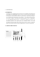
1. OPERATION 1.1 INTRODUCTION Your RAY53 has the capability to transmit and receive on all available US,International and Canada Marine VHF radiotelephone channels. There are channels that are FCC approved but may only be used by authorized stations for specific purposes, depending on the type of vessel (commercial or noncommercial.) Refer to Table 1-1 . These table list all of the marine VHF channels available in your RAY53 for Canada,International and U.S. radiotelephone use.
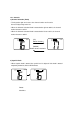
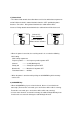
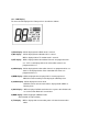
1.2.1 Controls 1) Channel Selection (Knob) -. Turning to the right can increase the channel number and it can be decreased by turning to the left. -. When the Channel Selection Knob is rotated to the right at “88CH”, the channel number becomes “01CH”. -. When the Channel Selection Knob is rotated to the left at “01CH”, the channel number becomes “88CH”. VOL SQL NMEA (UP) VOL SQL NMEA Rotate clockwise (DOWN) Rotate counter clockwise 2) Squelch Knob -.
3) Volume Knob -. The volume knob controls the audio volume and is also switched to turn power on and off. When the knob is rotated clockwise from the “OFF” position,the power becomes “Turned On”. Being rotated clockwise,the audio volume will be increased. Being rotated counterclockwise,the audio volume will be decreased. VOL SQL (Volume UP) NMEA VOL SQL NMEA Rotate clockwise (Volume DOWN) Rotate counter clockwise -.
-. To begin All Scan while memory are being stored in,All Scan can be begun by pressing once more during flashing on the LCD. -. When SCAN/MEM key is continuing to be pressed for more than three seconds, Alarm 1 is heard and Memory of the current channel can be stored/canceled.(When the current channel is stored,the current channel will be canceled. When no other channel is stored, the current channel will be stored. 5) WX/INT key -.
8) PTT Key(Microphone) -. When pressed,puts the radio into the transmit mode If the current channel is Weather CH or the channel prohibitted from TX, Alerm 2 is heard and PTT key cannot be used. If the PTT key is pressed continuously for over five minutes,transmission is forcibly inhibited and Alarm 2 is heard until the PTT key is released. 9) UP key(Microphone) -. The UP key is used to move the channel numbers up(+1). If the UP key is continuously pressed for over 0.
1.2.2 LCD Display The items of LCD display on the Front panel are described as follows 1) DSC display: Will be displayed when DSC mode is entered. 2) WX display : Will be displayed when Weather CH is entered. Will be displayed when Tri monitor mode is entered. 3) INT display : Will be displayed when International channels are programmed for use. “INT” is not displayed when US or Canadian channels are programmed for use. 4) CAN display: Will be displayed when Canadian channels are programmed for use.
10) 1 W display: Will be displayed when the transmitter circuits are providing 1 Watt of power to the antenna. When the transmitter is supplying 25 Watt to the antenna, “1 W” will be extinguished. 11)VOL, Bar Graph display: The Vol. bar graph shows the level of volume of the audio output to the speaker. The volume means to be larger when the dot of the bar graph become increased to the right. 12) SQL,AUTO : The Squelch bar graph shows the depth of squelch.
1.3 OPERATING PROCEDURES 1.3.1 Turning the Power On 1) Rotate the VOLUME knob clockwise to turn the radio on. 1.3.2 Setting the Volume 1) Rotate the VOLUME knob for the disired volume level. 1.3.3. Setting the Power Output 1) Simply press the “MON 1/25” key for two seconds to toggle between 1 Watt output and 25 Watt output. When “1 WATT” is displayed,the output power is 1 Watt. If “1 WATT” is extinguished, 25watts is being output.
When WX/INT key is pressed and held for over 2 seconds, one frequency mode can be changed to the other frequency mode and Alerm 1 is heard.: For example: When USA mode is in use,it can be changed to CANADIAN mode by doing above operation. When Canadian mode, it can bew changed to International mode. When International mode,it can be changed to USA mode. The last changed frequency mode can be memorized. When the power is turned on,the last memorized frequency mode can be used.
2) When 16/9 key is pressed and released again during “P” is diplayed, Alerm 1 is heard and the channel will be returned to the privious Working CH. When the channel is changed by UP/DOWN key during Priority CH is displayed, “P” display will be eliminated and Workimg CH will be in use. 3) When 16/9 is continueously pressed for over 2 seconds, Alerm 1 is heard and Priority channel can be changed either 16CH or 9CH.
radio will resume scanning. While the radio is scanning ALL-Scan,”SCAN” is displayed on the LCD. To cancel the scan mode,press the SCAN/MEM key while the radio is scanning. 2) Memory Scan mode If one or more channels are stored in memory,when the SCAN/MEM key is pressed and released, the audible beep sound 1 is heard and “SCAN” and “MEM” will begin to flash simultaneously on the LCD for 3 seconds.
VOL SQL NMEA VOL SQL NMEA WX MON VOL SQL NMEA MON MON WX Dual Monitor WX Tri Monitor Dual Watch operation -. “MON” is displayed on the LCD. -. Working CH number is displayed at Channel Display(Large) on the LCD. -. Priority CH(16CH or 9CH) number is displayed at Channel Display(Small) on the LCD. . If the signal of Working CH is detected, the Channel Display(Small) will be extinguished and the monitor will stop temporarily. Then the Receiver will be done for 7 seconds.
extinguished and the monitor will stop temporarily. Then the Receiver will be done for 7 seconds.( Even if there is no carrier for thse 7 seconds, the monitor will stop for 7 seconds.) After 7 seconds is passed,the radio will monitor Priority CH. -. If the carrier of Private CH is detected, the Priority CH number is displayed at the Channel Display(Large) and the Channel Display(Small) will be extinguished and the monitor will stop temporarily.
Carrier Detection at Weather CH (Alert is received) VOL SQL NMEA VOL SQL VOL SQL NMEA MON MON MON WX WX WX Carrier is detected NMEA Alert is not detected at Weather CH VOL SQL NMEA WX Alert is detected "WX" flash Exit Monitor mode 1.3.11 The key opeartion during the monitor operation. -. When PTT key is pressed,the monitor will stop and the transmission will be done at the stopped channel.
VOL SQL NMEA VOL SQL NMEA MON TX WX Press PTT key at Priority CH Priority CH is transmitted VOL SQL NMEA TX Press PTT key at Working CH Press PTT key at Weather CH Working CH is transmitted -. When SCAN/MEM key , MON/1/25 key or UP/DOWN key is pressed, Alerm 1 is heard and the monitor will stop and then Workimg CH will be in use.
-. When 16/9 key is pressed, Alerm 1 is heard and Scan operation will stop and then Priority CH will be in use. VOL SQL NMEA MON Stop monitor mode VOL SQL NMEA Switch to Priority CH -. Even if the Channel Selection knob is operated,there is no change. 1.3.12 The operation for Weather Alert detection(Alert Tone : 1050 Hz) Alert detection checks the output power from Alert detection IC as following timing. 100msec 10msec 0 2 4 6 25msec 8 10 11 12 13 14 15 16 17 18 -.
VOL SQL NMEA MON Alert tone is detected VOL SQL NMEA "WX" flash and Alarm 3 is heard WX WX 2. When alert tone is detected at Weather CH, “WX” display flashes every 0.5sec. (Alarm 3 is not heard) VOL SQL NMEA Alert tone is detected VOL SQL NMEA "WX" is flashing WX WX The operation by any keys after alert detection. -. When either PTT key,SCAN/MEM key or MON/1/25 key is pressed, Alarm 2 is heard to prohibit keys from using. -.
1) Own Ship’s ID Entry(Own Ship’s MMSI Entry) To operate the RAY53 in the DSC mode,Own Ship’s ID must be registered in advance. The registration procedure is as follows. 1. * If the former ID has been entered, Own Ship’s ID cannot be entered and Alarm 2 is heard. There should be no MMSI number in the unit when shipped. It is necessary for re-enter Own ship’s ID to delete the former ID by Own Ship’s ID Clear. *If there is no former ID, Alarm 1 is heard and Own Ship’s ID can be entered. 2.
-. If the number is entered correctly, the entered number becomes Own Ship’s MMSI by pressing DSC key for 2 seconds and the audible beep sound 1 is heard,then the DSC mode is exited and returned to Working CH. 4. Entry of number is done by Channel Selection knob. The number cannot be input by UP/DOWN key on the Microphone. The stored data can be memorized only by DSC key The stored data cannot be memorized by the other key operations and cannot be done when the power is turned off on the way. 5.
Channel Display(Large) is representative of the MMSI number itself and Channel Display(Small) is representative of the position in the 9 digit. -. When the Channel Selection knob is rotated, Channel Display(Large) shows the MMSI number is increased/decreased as “0” base.( 0 to 9 can be selected) -. MMSI number is selected by knob being rotated. When SCAN/MEM key(DSC key) is pressed, the audible beep sound 1 is heard and the selected number can be memorized.
6’ If the operator would like to resistor Other ship’s MMSI No.only without attempt of transmission, the last used(before registration of MMSI) CH will be displayed by pressing 16/9 key at this stage. 7. -. Working Channel can be selected by rotating Channel Selection knob. -. When SCAN/MEM key(“DSC” key) is pressed and released, the audible beep sound is heard and the selected number can be memorized as Working Channel number. 8. If the operator would like to resistor Other ship’s MMSI No.
10. The way to CLEAR Other ship’s MMSI No. There are two ways to clear Other Ship’s MMSI No. 1) To turn the unit on with pressing and holding SCAN/MEM key simultaneously. Alarm 1 is heard and “CL” is displayed at Channel Display(Large). Or 2) To turn the radio on with pressing and holding SCAN/MEM key and 16/9 key Simultaneously. Alarm 1 is heard and “CL” is displayed at Channel Display(Large). (Own Ship’s ID No. is also CLEAR by doing this operation.) 3) Other ship’s MMSI previously entered.
5’ Press and release WX/INT key if you do not have to check the MMSI number again , 6’ the LCD displays “DSC”, “ --- ---“,(Large Channel Display) and “w”(Small Channel Display) which means the unit is ready and waiting for input of Calling CH . 8. (If you would like to enter the different Other Ship’s MMSI number manually), 1. To rotate channel selection knob from the stage of the above 4(“MEM”,”DSC”,”0” and “1”) ,then the different other ship’s MMSI number can be set.
----Æ Channel Display(Large) displays 70CH. ----Æ “In” is flashing at Channel Display(Small) which means the unit is ready to receive Individual Ship’s Call. ----Æ “TX” is flashing, which means the unit is ready to receive Individual Ship’s Call. 4. To transmit the response by pressing PTT key. After transmission,the unit will switch to instructed Channel number and DSC mode will be exited. ----ÆWhen DSC mode is exited, “DSC” is eliminated. ----ÆChannel Display(Large) display the selected Channel number.
When “Individual Ship’s Call” is selected, Channel Display(Small) displays “In”. When “All Ship’s Call” is selected, Channel Display(Small) displays “AS”. 5. After selection of All Ship’s Call”,when SCAN/MEM key(“DSC” key) is pressed, the audible beep sound 1 is heard and the unit is ready to transmit “All Ship’s Call” ----Æ “TX” is flashing on the LCD which means that Transmission is ready. ----Æ Channel 70 is displayed at Channel Display(Large).
----Æ “As” is flashing at Channel Display(Small) which means the unit is ready to receive All Ship’s Call. 2. After the unit received “All Ship’s Call”, when SCAN/MEM key(“DSC” key) is pressed, the audible beep sound 1 is heard and the unit will switch to the 16CH of Working CH and then “DSC” mode will be exited. ----Æ When “DSC” mode is exited, “DSC” is eliminated from the LCD. ----Æ Channel display(Large) displays 16CH of Working CH. ----Æ Channel Display(Small) is eliminated.
----Æ Distress signal can be automatically transmitted.( “TX” is displayed on the LCD during transmitting.) 4. After transmitting Distress signal,the unit will wait for an acknowledgement from the other ship. ----Æ Channel Display(Large) displays 70CH. ----Æ Channel Display(Small) displays “16” which means the channel after receipt of an acknowledgement will be 16CH. ----Æ “TX” will be eliminated. 5.
----Æ “d ” is flashing at Channel Display(Small) which means the unit is ready to receive Distress Call. After the unit received “Distress Call”, when “DSC” key is pressed and released, Alarm 1 is heard and the unit will switch to the 16CH of Working CH and then “DSC” mode will be exited. ---Æ When “DSC” mode is exited, “DSC” is eliminated from the LCD. ---Æ Channel Display(Small) is eliminated3. DSC Watch mode can be activate by doing following operat. 8) DSC WATCH Mode/ON OFF operation 1.
To rotate Channel Selection Knob to the left, the unit will be displayed back to the Above 4). The display will be done as 6) Æ 4) Æ 2) Æ 6). 7) By pressing SCAN/MEM key, DSC Watch mode can be selected either ON or OFF. 8) To press SCAN/MEM key and WX/INT key simultanously, the unit return to the last Used display before the above 1) display. 9) When Power is re-activate on, the unit will start in the mode last used.(On or OFF).
2. SPECIFICATIONS Transmitter Channels All available US,International and Canada VHF Marine band Frequency Stability +/- 10PPM(+/- 0.001%) (-20° C to +50° C) Frequency Range 156.025 to 157.425MHz Channel Spacing 25 kHz Increments Power Output 25 Watts switchable to 1 Watt into 50 Ohms at 13.6 VDC Modulation Frequency modulated 16F3 (+/-4.5kHz at 1000Hz) Modulation Audio Response Shall not vary +1/-3 dB from true 6 dB pre-emphasis from 300 to 2500Hz, reference 1000Hz.
Receiver Channels All available US,International,Canada VHF Marine Band Frequency Range 156.025 to 163.275 MHz in 25 kHz increments Frequency Stability +/- 10 PPM(+/- 0.001%) from -20° C to +50° C Usable Sensitivity 0.3µV for 12dB(SINAD) Squelch Sensitivity 0.2µV or better Threshold 1.
Duty Cycle Continuous, 80% receive, 20% transmit (max 10 min, @25° C ) Humidity 100% at 50°C for 8 hours Radio Dimensions Height 55 mm(2.17 inches) Width 145mm(5.7 inches) Depth 160mm(6.3 inches) Weight Approx.
3. TECHNICAL DESCRIPTION 10.1 General The RAY53 can be considered as consisting of two major sections. -. The control section(consisting of the front panel controls ,LCD display,and CPU -. The transmitter/Receiver/PLL section. 10.2 The Control Section . The heart of the control section is the CPU,which is IC201 located on the CNTL PCB. The CPU controls all of the following items: -. Controls the Squelch circuit by detecting a busy signal from the 2nd IF circuit IC3 on the RF PCB. -.
make 25KHz-reference frequency. Transmit frequency is generated on the Inductor and Capacitor circuit with connected to IC2 pin 4,5. The frequency control voltage, which is output from IC2 pin 7, will be input into Variable Capacitance Diode(D6) on Inductor and Capacitor circuit. The receiver local frequency is generated on the Inductor and Capacitance circuit with connected to IC2 pin 20, 21.
3.4.3 APC Circuit Diode D4 is monitoring a part of the power module’s(IC5) output. The monitoring signal will be output to IC5 via switching transistor Q8 and display the “TX ON” and the LCD. The output voltage from IC5 controls the RF power to keep the RF output at a constant level. 3.4.4 DSC Signal Treatment In DSC mode at CH70,a sequence signal from CPU is input to MODEM IC(IC11) and converted to an analog signal.
3.5.4 2nd Intermediate Frequency Circuit The 1st IF signal is added to IC3 and converted to 2nd IF signal. The 2nd IF signal goes through F2 and amplified in the IC3 and then through discriminator CD1 and the demodulated AF signal is output from IC3. 3.5.5 Low Frequency Circuit The AF signal demodulated in the IC3 goes through the de-emphasis circuit consisting of operational amplifier IC4(A) and R127 and C45.
4. ALIGNMENT for RAY53 4.1 PLL Adjustment(Receiver) 1.1 Connect the power supply(13.6V, 10) to the power line. 1.2 Set the radio on CH16(156.800MHz) and set it to Receiver mode. 1.3 Connect the reed terminal of a digital voltmeter or high impedance tester to Test point(TP2) on RF PCB and set it to DC voltage range. 1.4 Adjust variable coil (T1) in the RF PCB(in the VCO shield case) and set the DC voltage to 1.3V+/-0.1V. 4.2 PLL Adjustment(Transmitter) Connect the power supply (13.
linear detector. 4.3.3 Connect the audio oscillator and PTT test Assy to Connector (J203) No.1 pin in CNTL PCB. Set the audio oscillator to –18dBm and set the frequency to 1KHz And then set it to transmitter mode. 4.4.4 Adjust Variable Resistor(VR4) in the RF PCB to set the deviation displayed on FM linear detector to 4.2kHz+/-0.1kHz. 4.4.5 Set the audio oscillator to –38dBm and set the frequency to 1kHz. Confirm that the deviation on FM linear detector should be 3.0kHz+/-0.5kHz. 4.5 4.5.
5. ELECTRICAL CONNECTIONS 5.1 DC Power, External Speaker Connections and NMEA Input The 6 feet long power cable assembly consists of the DC power cable and the external speaker cable. The DC power cable is composed of RED(+) and BLACK(-) wires, and the external speaker cable has YELLOW(+) and GREEN THICK(-) wires and NMEA Input has BLUE(+) and PURPLE(-). The RED(+) wire with an in-line fuse(10 amps.) and the BLACK(-) wire of the 6 pin connector cable are used for connecting the RAY53 to the ship’s 13.
10 amp.in-line fuse located in the RED(+) wire will open. Check the input power leads for correct polarity with a VOM(volt/ohm meter),reconnect the leads observing correct polarity,and replace the fuse. Use the same rate and type fuse. -The RAY53 accepts NMEA 0183 data from a GPS or Loran navigator to provide Lat/Lon position information that is transmit during DSC Distress Call mode. The NMEA sentences that could provide positional data,by order of priority are: GGA.RMC,RMA,and GLL. 5.
obtain maximum range. -. Use an antenna with highest possible gain characteristics. -. If you must extend the length of the coaxial cable between the antenna and the Radio, use a coaxial cable designed for the least amount of power loss over the entire cable length. -. Keep the coaxial cable between the radio and antenna as short as possible. 5.
USA Frequency DATA CH TX Frequency 1 2 3 4 5 6 7 8 9 10 11 12 13 14 15 16 17 18 19 20 21 22 23 24 25 26 27 28 60 61 62 63 64 65 66 67 68 69 70 71 156.050 RX PWR Frequency 156.050 156.150 156.150 156.250 156.300 156.350 156.400 156.450 156.500 156.550 156.600 156.650 156.700 156.800 156.850 156.900 156.950 157.000 157.050 157.100 157.150 157.200 157.250 157.300 157.350 157.400 156.250 156.300 156.350 156.400 156.450 156.500 156.550 156.600 156.650 156.700 156.750 156.800 156.850 156.900 156.950 157.
72 156.625 156.625 INT Frequency DATA CH 1 2 3 4 5 6 7 8 9 10 11 12 13 14 15 16 17 18 19 20 21 22 23 24 25 26 27 28 60 61 62 63 64 65 66 67 68 69 TX Frequency RX PWR Frequency 156.050 160.650 156.100 160.700 156.150 160.750 156.200 160.800 156.250 160.850 156.300 156.300 156.350 160.950 156.400 156.400 156.450 156.450 156.500 156.500 156.550 156.550 156.600 156.600 156.650 156.650 2 156.700 156.700 156.750 1 156.800 156.800 156.850 156.850 3 156.900 161.500 156.950 161.550 157.000 161.600 157.050 161.
70 71 72 156.525 156.575 156.625 156.525 156.575 156.625 4 CAN Frequency DATA CH TX Frequency 1 2 3 4 5 6 7 8 9 10 11 12 13 14 15 16 17 18 19 20 21 22 23 24 25 26 27 28 60 61 62 63 64 65 66 156.050 156.100 156.150 156.200 156.250 156.300 156.350 156.400 156.450 156.500 156.550 156.600 156.650 156.700 156.800 156.850 156.900 156.950 157.000 157.050 157.100 157.150 157.200 157.250 157.300 157.350 157.400 156.025 156.075 156.125 156.175 156.225 156.275 156.325 RX PWR Frequency 156.050 156.100 156.
67 68 69 70 71 72 156.375 156.425 156.475 156.525 156.575 156.625 156.375 156.425 156.475 156.525 156.575 156.625 2 4 NOTE: 1. Transmitter is automatically disable on channel 15,75 and 76 in all modes. 2. 1 Watt initially. User can override to 25Watts via front panel controls. 3. 1 Watt Only 4. Channel 70 is now used for Digital Selective Calling only.