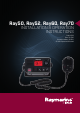
Ray50, Ray52, Ray60, Ray70 INSTALLATION & OPERATION INSTRUCTIONS English (EN) Date: 03-2016 Document number: 81356-3 © 2016 Raymarine UK Limited
Trademark and patents notice Raymarine, Tacktick, Clear Pulse, Truzoom, HSB, SeaTalk, SeaTalkhs, SeaTalkng, Micronet, Raytech, Gear Up, Marine Shield, Seahawk, Autohelm, Automagic, and Visionality are registered or claimed trademarks of Raymarine Belgium. FLIR, DownVision, SideVision, Dragonfly, Quantum, Instalert, Infrared Everywhere, and The World’s Sixth Sense are registered or claimed trademarks of FLIR Systems, Inc.
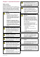
Contents Chapter 1 Important information.......................... 7 Safety notices.............................................................. 7 General Information ..................................................... 8 Chapter 2 Document and product information........................................................... 11 2.1 Document information .......................................... 12 2.2 Product information ..............................................
12.1 Raymarine product support and servicing ............ 88 12.2 Viewing product information ................................ 89 12.3 Learning resources............................................. 89 Chapter 13 Technical specification.................... 91 13.1 Technical specification — Ray50 / Ray52 ............ 92 13.2 Technical specification — Ray60 ......................... 93 13.3 Technical specification — Ray70 ......................... 94 13.4 Radio usage .........................................
Chapter 1: Important information Warning: Antenna isolation Safety notices To prevent galvanic corrosion your antenna must be isolated from any vessel metalwork using a suitable insulated e.g. plastic, mounting bracket. Certified Installation Raymarine recommends certified installation by a Raymarine approved installer. A certified installation qualifies for enhanced product warranty benefits.
Caution: Product cleaning When cleaning products: can be determined by turning the equipment off and on, the user is encouraged to try to correct the interference by one of the following measures: • If your product includes a display screen, do NOT wipe the screen with a dry cloth, as this could scratch the screen coating. 1. Reorient or relocate the receiving antenna. • Do NOT use abrasive, or acid or ammonia based products. 3.
European licensing requirements Regulations in some areas require that an Operator’s license is obtained before operating a VHF radio. It is your responsibility to determine whether a license is required in your area before operating this equipment. Additional information – Ray50 / Ray52 The following additional information is required for completing a license application in Canada and the US.
For optimum EMC performance we recommend that wherever possible: • Raymarine equipment and cables connected to it are: – At least 1 m (3 ft) from any equipment transmitting or cables carrying radio signals e.g. VHF radios, cables and antennas. In the case of SSB radios, the distance should be increased to 7 ft (2 m). – More than 2 m (7 ft) from the path of a radar beam. A radar beam can normally be assumed to spread 20 degrees above and below the radiating element.
Chapter 2: Document and product information Chapter contents • • 2.1 Document information on page 12 2.
2.1 Document information Document conventions This document contains important information related to the installation of your Raymarine product. The following conventions are used throughout this document when referring to: The document includes information to help you: Type • plan your installation and ensure you have all the necessary equipment; Procedures for Select Set-Up. performing specific tasks using the product’s user interface.
Product documentation 2.2 Product information The following documentation is applicable to your product: The Ray50, Ray52, Ray60 and Ray70 are 12 V dc, Class D Digital Selective Calling (DSC) VHF radios. DSC enables you to make a selective call to a specific radio, and to transmit and receive position information to and from the selected radio. DSC also allows transmission of a distress alert to all radios within range at the touch of a button.
Ray50 / Ray52 / Ray60 / Ray70
Chapter 3: Planning the installation Chapter contents • • • • • • • • • • • 3.1 Installation checklist on page 16 3.2 Parts supplied – Ray50 / Ray52 on page 16 3.3 Parts supplied – Ray60 / Ray70 on page 17 3.4 Tools required for installation on page 17 3.5 Software updates on page 18 3.6 System integration — Ray50 / Ray52 on page 19 3.7 System integration — Ray60 / Ray70 on page 20 3.8 System protocols on page 21 3.9 General location requirements on page 22 3.10 Mounting options on page 23 3.
3.1 Installation checklist 3.2 Parts supplied – Ray50 / Ray52 Installation includes the following activities: The parts listed below are supplied with the Ray50 and Ray52 radios. Installation Task 1 Plan your system. 2 Obtain all required equipment and tools. 3 Site all equipment. 4 Route all cables. 5 Drill cable and mounting holes. 6 Make all connections into equipment. 7 Secure all equipment in place. 11 8 Power on and test the system.
3.3 Parts supplied – Ray60 / Ray70 3.4 Tools required for installation The parts listed below are supplied with the Ray60 and Ray70.
3.5 Software updates Checking software versions Raymarine periodically releases software updates for its products. These updates can provide new and enhanced features and also improve product performance and usability. You should ensure that you have the latest software for your products by regularly checking the website for new software. LightHouse™ powered MFDs can be used to check and update the software of compatible products.
3.6 System integration — Ray50 / Ray52 Your VHF radio can be connected to the following marine electronics devices. 1 2 3 D13294-2 Item Device type Maximum quantity 1 Passive speaker 2 GPS Receiver Suitable devices Connections 1 3rd party 5 W (4 Ω) / 2.
3.7 System integration — Ray60 / Ray70 Your VHF radio can be connected to the following marine electronics devices. 1 2 4 3 0 0 5 6 D13295-1 Item Device type Maximum quantity Suitable devices Connections 1 Fistmic 1 Fistmic Front connector or rear connector via adaptor cable. 2 Handset 1 Ray60 / Ray70 Raymic Handset Rear connector 3 Passive speaker 1 per station 3rd party 5 W (4 Ω) / 2.5 W (8 Ω) passive speaker RCA audio connection 4 Loud hailer 1 –Ray70 only.
3.8 System protocols Your product can send and receive position information, e.g. latitude and longitude using any of the following protocols: • SeaTalkng passed in ‘sentences’, each of which has a three letter sentence identifier. It is therefore important when checking compatibility between items that the same sentence identifiers are used some examples of which are: • NMEA 2000 • VTG - carries Course and Speed Over Ground data. • NMEA 0183 • GLL - carries latitude and longitude.
3.9 General location requirements When selecting a location for the unit it is important to consider a number of factors. 1 2 Antenna mounting and EME exposure 3 Ensure that the antenna is connected to the radio before transmission. Raymarine declares a Maximum Permissible Exposure (MPE) radius of 1.5 metres (4.9 ft) (per OET Bulletin 65) for this system, assuming 25 watts output to an omnidirectional antenna of 3dBi gain or less.
• Use cable supports to prevent stress on connectors. Electrical interference Select a location that is far enough away from devices that may cause interference, such as motors, generators and radio transmitters/receivers. 3.10 Mounting options The product can be mounted in the following configurations. 1 2 3 4 Power supply Select a location that is as close as possible to the vessel’s DC power supply. This will help to keep cable runs to a minimum. D13203-1 1. Table top mount 2. Overhead mount 3.
3.11 Product dimensions Ray60 and Ray70 dimensions (bracket mount) 133 mm (5.2 in.) Ray50 / Ray52 product dimensions The Ray50 / Ray52 can be panel mounted or bracket mounted. Ray50 / Ray52 dimensions (panel mount) 168 mm (6.6 in.) 156 mm (6.1 in.) 134 mm (5.3 in.) 88.5 mm (3.5 in.) 226 mm (8.9 in .) 39.75 mm (1.6 in.) 25 mm (1 in .) 59 mm (2.3 in.) 204.6 mm (8 in .) 21.5 mm (0.85 in.) 143.6 mm (5.7 in.) D13171-1 Fistmic dimensions 25 mm (1 in .) 97.6 mm (3.8 in.
Chapter 4: Cables and connections Chapter contents • • • • • • • • • • • • • • 4.1 General cabling guidance on page 26 4.2 Connections overview — Ray50 / Ray52 on page 27 4.3 Connections overview Ray60 / Ray70 on page 27 4.4 Ray60 / Ray70 primary and second station connectors on page 28 4.5 Power connection on page 28 4.6 Connecting handsets and cables on page 30 4.7 Fistmic connection Ray60 / Ray70 on page 31 4.8 Second handset station — Ray60 / Ray70 on page 32 4.9 Handset extension cables on page 32 4.
4.1 General cabling guidance Cable types and length It is important to use cables of the appropriate type and length • Unless otherwise stated use only standard cables of the correct type, supplied by Raymarine. • Ensure that any non-Raymarine cables are of the correct quality and gauge. For example, longer power cable runs may require larger wire gauges to minimize voltage drop along the run. • Always use an RS232/NMEA converter with optical isolation on the signal lines.
4.2 Connections overview — Ray50 / Ray52 4.3 Connections overview Ray60 / Ray70 The following connections are available on the Ray50 / Ray52. The following connections are available on the Ray60 and Ray70. 1 2 3 1 4 2 3 5 4 5 6 D13296-1 6 1. Ground point — DO NOT USE! 7 2. SeaTalkng® 8 9 3. Antenna 4. RCA Audio lead 5. NMEA 0183 6. Power supply connection D13297-2 1. Primary station 8 pin connector 2. Second station 12 pin connector 3. Ground point — DO NOT USE! 4. SeaTalkng® connector 5.
4.4 Ray60 / Ray70 primary and second 4.5 Power connection station connectors The connectors below are used to connect the supplied Fistmic and / or the optional Raymic Handset to the Base station.
Warning: Chassis grounding A Do NOT ground this product using the chassis ground terminal. Grounding this product to a vessel’s RF ground may cause galvanic corrosion. Power distribution B Recommendations and best practice. • The product is supplied with a power cable. Only use the power cable supplied with the product. Do NOT use a power cable designed for, or supplied with, a different product.
Grounding 4.6 Connecting handsets and cables Ensure that you observe the separate grounding advice provided in the product’s documentation. Follow the steps below to connect handsets and extension cables together. 1. Ensure the cable connectors are correctly orientated. 2. Ensure connectors are fully inserted. 3. Tighten locking collars by Rotating clockwise.
4.7 Fistmic connection Ray60 / Ray70 Connecting the Fistmic – Ray60 / Ray70 The Fistmic should primarily be connected to the front Fistmic connector. Using an adaptor cable the Fistmic can be connected to the rear second station connector, this is useful when the Fistmic is required to be slightly farther away from the base station than the Fistmic’s cable allows. The Fistmic can be connected directly to the connector on the front of the unit.
4.8 Second handset station — Ray60 / Ray70 The Raymic handset accessory can be connected to the second station connector located on the rear of the radio, this will create a second fully functional station. 1 4.9 Handset extension cables Handset station cabling can be extended using approved extension cables. The maximum length of cable from the Handset to the Base station should not exceed 50 m (164 ft) 3 2 4 5 6 7 D13300-1 1. Primary station. 2.
4.10 SeaTalkng® connection The product can interface with Raymarine® GPS or GNSS receivers and Raymarine® multifunction displays using the SeaTalkng® connection. 1 2 4 0 3 0 5 D13218-1 6 SeaTalkng D13293-1 1. Ray50 / Ray52 / Ray60 / Ray70 2. Optional Raymic handset station (Ray70 and Ray70 only) 1. Rotate the SeaTalkng® connector’s locking collar anti clockwise, to the unlocked position. 2. Ensure the spur cable connector is correctly orientated. 3.
4.11 NMEA 0183 connection 4.12 Connecting an antenna The NMEA 0183 wires can be used to connect the unit to a 3rd party GPS/GNSS receiver or multifunction display. The radio must be connected to a suitable antenna (not supplied). The antenna connection must be protected so it cannot come into contact with any bare metal (which may be grounded). A protective boot is supplied that can be used to ensure isolation of the antenna connection. 1 + 2 - 3 + 4 D13219-1 1 2 3 4 5 6 1.
4.13 Passive speaker connection 4.14 Loud hailer connection A passive speaker can be connected using the RCA lead on the radio or on the handset adaptor cable. A single loud hailer can be connected to the radio using the dedicated loud hailer wires. D13301-1 1 + 2 D13219-1 1 (+) Hailer wire (Purple) 2 (-) Hailer wire (Gray) Loud hailer wires should be connected securely and covered to prevent corrosion.
Ray50 / Ray52 / Ray60 / Ray70
Chapter 5: Location and mounting Chapter contents • • • • • • 5.1 5.2 5.3 5.4 5.5 5.
5.1 Bracket mounting 5.2 Ray50 / Ray52 Panel mounting Follow the steps below to mount the product on it’s bracket. Removing the mounting hole covers — Ray50 / Ray52 Before mounting the unit ensure that you have: Before the Ray50 / Ray52 can be panel mounted the mounting hole covers must be removed. • Selected a suitable location, ensuring there is nothing behind the mounting surface that may be damaged when drilling. • Identified the cable connections and route that the cables will take.
Note: The supplied gasket provides a seal between the unit and a suitably flat and stiff mounting surface or binnacle. The gasket should always be used. It may also be necessary to use a marine-grade sealant if the mounting surface or binnacle is not entirely flat and stiff or has a rough surface finish. D13207-1 1. Check the selected location for the unit. A clear, flat area with suitable clearance behind the panel is required. 2.
5.3 Ray60 / Ray70 Panel mounting Drilling out the mounting holes – Ray60 / Ray70 Before panel mounting the product the mounting holes must be drilled out. Guides for the mounting holes can be found in the corners of the unit, under the front bezel. x4 D13209-1 1. Using a drill and a 4 mm (5/32) drill bit, drill out the 4 mounting holes. Holes should be drilled from the front of the unit, taking care not to damage the unit by applying too much force to the drill.
5.4 Fistmic / Handset mounting The Fistmic and optional Handset can be mounted by following the steps below. Whilst only the Fistmic is pictured below the steps are identical when mounting the Handset using the mounting clip. Before mounting the unit, ensure that you have: • Selected a suitable location, ensuring there is nothing behind the mounting surface that may be damaged when drilling. 5.
5.6 Pass-through panel kit mounting When installing the Fistmic or the optional Raymic handset, the pass-through panel kit should be used to secure the cable to any panels the cable has to pass through. to another pass-through panel mounting plate connector. Note: Drill bit, tap size and tightening torque is dependent on the thickness and type of material the unit is to be mounted on.
Chapter 6: Getting started Chapter contents • • • • • • • • • • • • • • • • • • 6.1 Controls and interface on page 44 6.2 Ray60 / Ray70 handset controls on page 44 6.3 Powering the unit on on page 45 6.4 Powering the unit off on page 45 6.5 Homescreen overview on page 46 6.6 Shortcut list on page 48 6.7 Shared Brightness on page 48 6.8 Initial startup on page 49 6.9 Accessing the menu on page 50 6.10 Selecting a language on page 50 6.11 Switching on the AIS receiver — Ray70 on page 51 6.
6.1 Controls and interface 6.2 Ray60 / Ray70 handset controls The controls and interface available are as follows: The optional handset for the Ray60 and Ray70 VHF radios includes the following controls: Base station 1 2 1 2 3 4 3 5 6 7 8 9 11 11 4 5 6 7 8 10 D13220-2 12 1. Built-in speaker 13 2. Rotary knob / OK push button — Press knob in to access menu / DSC functions and to confirm selections.
6.3 Powering the unit on 6.4 Powering the unit off With the radio connected to a power supply the power button is used to switch the radio on and off. 1. Press the Power button to power-up the radio. With the unit powered on: 1. Press and hold the Power button for approximately 3 seconds to power the unit off. The startup is displayed. Ray60 Software V1.00 MMSI: 123456789 OK The startup screen will automatically time-out after 5 seconds. 2.
6.5 Homescreen overview • d = Duplex — Duplex channels use separate frequencies to transmit and receive. The information below describes the on-screen characters and symbols which the radio displays on the main screen and what they mean. 4 5 7 Status bar symbols The status bar is used to display icons that indicate the radio’s status. 1 2 9. Optional text — Provides extra user guidance INT Scanning...(All + 16) a 50º51’.615 N 001º14’.
Symbol Name Description Symbol DSC Indicates that a DSC call has been received Name Sub-options * Scan Mode • All channels • All channels + 16 • Saved channels GPS Fix • Saved channels + 16 Indicates if the radio has a GPS/GNSS fix. • Edit saved channels ** Hail/Fog/Intercom Main menu overview • Hailer • Fog horn • Intercom The main menu is accessed by Pressing the OK button from the Homescreen.
6.6 Shortcut list 6.7 Shared Brightness Pressing the Power button once while the radio is switched on will open the Shortcuts list. The Shortcuts list can be used to adjust the brightness, contrast and access frequently used functions. You can set up Shared Brightness groups which enables simultaneous brightness adjustment the all units that are part of the same group.
Adjusting the Brightness setting will now change the brightness of all products assigned to that group. 6.8 Initial startup Unless your radio has been pre-programmed; the first time you power-up your radio you will be requested to select certain options. With the exception of your MMSI and ATIS ID, you will also be requested to enter these options after a factory reset. After acknowledging the startup screen, unless previously set you will be prompted to make the following selections: 1.
6.9 Accessing the menu 6.10 Selecting a language The radio’s various options and settings are contained within the menu. The language the radio uses can be changed. From the Main menu: 1. Select Set-up. 2. Select Language. The languages available are: • English (default) — English • Español — Spanish • Français — French • Deutsch — German • Italiano — Italian 3. Select the language that you want the radio to be set to. D13228-1 From the Homescreen. 1. Press the Rotary knob’s OK push button.
6.11 Switching on the AIS receiver — Ray70 The Ray70’s AIS receiver can be switched on or off. From the Main menu: 1. Select Set-up. 2. Select AIS. 3. Select On. 6.12 Selecting a network type When connecting your radio to other devices it is important to ensure you select the network connection and type that you want data to be transmitted over. From the Main menu: 1. Select Set-up. 2. Select Network output.
6.13 Entering your MMSI number ii. if the number entered is not correct select No – Retry. To program your radio with your MMSI number follow the steps below. Caution: MMSI and ATIS ID entry You can only enter the MMSI number and ATIS ID once! 1 If you store an incorrect MMSI number or ATIS ID in your product, it will have to be reset by an authorized Raymarine® dealer. 2 3 Yes No 4 D13224-2 From the Set-up menu: (Menu > Set-up) 1. Select DSC set-up. 2. Select MMSI.
6.14 Entering your ATIS ID A unique ATIS ID must be entered before ATIS mode can be enabled. 1 9. The ATIS ID is displayed onscreen, check that it is correct, then: i. Select Yes – Save, or ii. if the number entered is not correct select No – Retry. Caution: MMSI and ATIS ID entry You can only enter the MMSI number and ATIS ID once! 2 If you store an incorrect MMSI number or ATIS ID in your product, it will have to be reset by an authorized Raymarine® dealer.
6.15 Changing the radio region Prior to using the radio you must set the Frequency band to the region your radio will be used in. From the Main menu: 6.16 Switching between high and low transmit power You can switch between high (25 W) and low (1 W) transmit power using the HI/LO button on the Fistmic. The transmit power can also be changed from the Set-up menu: Menu > Set-up 1. Select Power output. 2. Select Low for 1 W transmit power, or 3. Select High for 25 W transmit power. 1 2 3 4 D13326-2 1. 2.
6.17 GPS/GNSS setup If your radio includes an internal GPS/GNSS receiver or if your radio is connected to a GPS/GNSS receiver over NMEA 0183 or SeaTalkng®, the radio can display relevant GPS information. The following information can be displayed: • latitude • longitude • UTC time • COG and SOG When GPS/GNSS data is available the satellite icon is displayed onscreen.
6.18 Station priority - Ray60 and Ray70 The Ray60 and Ray70 can have both a Local Fistmic (connected to the front connector) and a Remote Handset (connected to the rear connector) station. The following rules apply to station priority: • The Local station always takes priority over the Remote station. • Unless a Distress call is in progress, any button press on the Local station will take control from the Remote station.
Chapter 7: Digital selective calling (DSC) Chapter contents • • • • • • • • • • • 7.1 Digital Selective Calling (DSC) on page 58 7.2 Distress calls on page 59 7.3 Urgency calls on page 61 7.4 Safety calls on page 62 7.5 Individual (routine) calls on page 62 7.6 Group calls on page 63 7.7 Position requests on page 64 7.8 Phonebook on page 64 7.9 Call logs on page 65 7.10 Test calls on page 65 7.
7.1 Digital Selective Calling (DSC) Traditional VHF radio systems require users to listen until someone speaks, and then determine whether the call is for them. DSC ensures that calls are received by alerting or announcing the intended recipient(s) first so they are ready to listen to the subsequent message on the relevant channel.
7.2 Distress calls down reaches zero the DSC distress call is transmitted. Making a designated distress call When making a Distress call you can specify the nature of the distress, if GPS data is not available you must also specify your coordinates. Note: Your radio must have an MMSI number saved before DSC functions can be used. From the Distress call menu: Menu > DSC Calls > Distress calls 1. Select a distress type from the list.
Cancelling a distress call after transmission A distress call can be cancelled after it has been transmitted. 1 DISTRESS CALL 00:04 Sinking 2 3 MMSI 123456789 Accept- Ch16 Showinfo 4 D13229-2 1. 2. 3. 4. 5. Select Options. Select Cancel distress. Select Yes to confirm cancellation. Select OK. Press and hold the PTT button and make a broadcast to all stations giving your vessel’s name, call sign and MMSI number and cancel the false distress alert Example: “All, Stations, All Stations, All Stations.
4. You MUST then notify the shore authorities by any means possible to relay the distress call. 7.3 Urgency calls Making an urgency call Manually relaying a distress call A distress relay should only be sent if: the person or vehicle in distress is unable to transmit the distress call itself, for example red flares sighted at night or the person or vehicle in distress is out of range of a CRS and you have already acknowledged the distress by voice message.
7.4 Safety calls 7.5 Individual (routine) calls Making a safety call Individual calls can be made to contacts saved in your phonebook or to any station by manually entering an MMSI number. Safety calls should be used when there is an important navigational warning or meteorological forecast/broadcast. Safety alerts can also be used for communications during search and rescue operations. From the All ships call menu: Menu > DSC Calls > All ships call. 1. Select Safety. 2.
4. If you rejected the call, select a reason for the rejection from the list. Confirmation of the acceptance or rejection of the call is displayed. If you have accepted the call then the radio will re-tune to the requested channel. 7.6 Group calls Group calls can be made to groups of vessels sharing the same Group MMSI numbers. Group calls are made by selecting a saved group contact from the Phonebook or by entering the Group MMSI number for the group you want to call.
7.7 Position requests 7.8 Phonebook The radio can request position information from any station capable of responding to the request. The phonebook can be used to save up to 100 contacts. Position requests can be sent to any contact stored in the Phonebook or by manually inputting the station’s MMSI number. You can add, edit and delete contacts stored in the phonebook. When connected to a Raymarine® multifunction display the position data from the request can also be display in the Chart application.
7.9 Call logs 7.10 Test calls All DSC calls are logged. A Test Call feature is available for the purposes of testing your DSC VHF radio for correct operation. The following call types are recorded in call logs: • distress • distress relay • distress acknowledgements • sent position requests • received position requests • group calls • all ship calls • individual routine calls The details below are recorded for each call: • MMSI number(s) (If a call is relayed up to 3 MMSI numbers can be recorded.
7.11 DSC set-up menu options The DSC set-up menu options can be accessed from the following menus: • Menu > DSC Calls > DSC set-up • Menu > Set-up > DSC set-up Menu item Description MMSI To enable the DSC functions on your radio you must enter your unique MMSI number. Auto channel change When automatic • On (default) channel change is • Off turned on the radio will automatically re-tune after 10 seconds to the requested channel when DSC calls are received.
Chapter 8: VHF operations Chapter contents • • • • • • • • 8.1 Watch modes on page 68 8.2 Scan Mode on page 68 8.3 Priority channels on page 69 8.4 Sensitivity on page 69 8.5 Private channels on page 70 8.6 Automatic Transmitter Identification System (ATIS) and Marcom-C mode on page 70 8.7 AIS — Ray70 on page 71 8.
8.1 Watch modes 8.2 Scan Mode Watch mode monitors priority channels and the currently selected channel. Scan mode enables automatic searching for channels that are currently broadcasting. There are 2 types of watch mode; Dual watch and Triple watch or Tri watch. Scan mode will search through available channels and stop when it finds a channel that is currently broadcasting. If the broadcast stops or is lost for more than 5 seconds then the scan will resume.
8.3 Priority channels 8.4 Sensitivity Channel 16 is the dedicated priority channel. The sensitivity level of the radio can be set to Local mode or Distant mode. The default secondary priority channel is channel 09. The second priority channel can be changed if desired. Switching between priority channels 1. Press the 16 / + button to switch between priority channels. Local mode decreases the receiver sensitivity in high traffic areas to reduce unwanted reception.
8.5 Private channels The radio may be able to receive additional Private channels depending on the country it is used in and whether the appropriate licenses are held.
8.7 AIS — Ray70 The Ray70 has a built in AIS receiver. With the built-in AIS receiver switched on AIS information can be sent to a connected Raymarine® MFD using either NMEA 0183 or SeaTalkng®. Note: If using the built-in AIS receiver and outputting over NMEA 0183, ensure that the baud rate is set to 0183 High speed: Menu > Set-up > Network output . Switching AIS on and off From the Set-up menu: Menu > Set-up. 1. Select AIS. Selecting AIS will switch the internal AIS receiver On and Off.
8.8 Set-up menu options The Set-up menu options can be accessed from the menu. Menu Description Options Display set-up Provides access to the display settings menu • Backlight • Shared brightness • Contrast • Homescreen display Language Enables selection of user interface language.
Menu Description Options ATIS set-up Enables you to switch ATIS mode on and • ATIS off and enter your ATIS ID. • ATIS ID Maintenance Enables you to view system details and functions that may be required during maintenance and troubleshooting. • About this unit • System reset • System test Display Set-up menu The following menu options are available form the Display Set-up menu. Menu Description Options Backlight Increases and decreases the LCD and button backlight level.
Ray50 / Ray52 / Ray60 / Ray70
Chapter 9: Hailer, Fog horn, and Intercom Chapter contents • • • • 9.1 9.2 9.3 9.
9.1 Hailer Fog Intercom menu 9.2 Loud Hailer — Ray70 The menu options available are determined by the device connected to your radio. The Ray70 can be connected to a Loud hailer. Menu name Connected devices Hail/Fog/Int Loud hailer and second station connected. Hailer/Fog Loud hailer connected, no second station Intercom Second station connected, no loud hailer Note: For simplicity the procedures in this section all refer to the Hail/Fog/Int menu.
9.3 Fog horn The fog horn function requires an optional loud hailer to be connected. Please check your product description to ensure a loud hailer can be connected. The fog horn function can be set to manual or to predefined automatic modes. In manual mode a continuous tone is sounded for as long as the PTT button is pressed. In automatic mode the selected tone will repeat every 2 minutes until interrupted or cancelled. In automatic mode the radio can be used as normal between the fog horn patterns.
9.4 Intercom — Ray60 and Ray70 The Intercom function is available when a second station is connected to your radio. The intercom function allows voice communication between the second (handset) station and the primary station. A call can be initiated from either station. Using the intercom From the Hail/Fog/Int menu: Menu > Hail/Fog/Int. 1. Select Intercom. The other station will ring. 2. Wait for the handset station to acknowledge the call. 3. Press and hold the PTT button and speak your message.
Chapter 10: Maintenance Chapter contents • 10.
10.1 Maintenance The Ray260 has no user serviceable parts or adjustments. Never remove the cover or attempt to service the product, doing so may invalidate your product warranty. To following preventive measures should be followed: • Although the product is waterproof, keep the unit as dry as possible. • If you remove a handset connection ensure the dust cap is fitted to the connector.
Chapter 11: Troubleshooting Chapter contents • • • • 11.1 11.2 11.3 11.
11.1 Troubleshooting The troubleshooting information provides possible causes and corrective action required for common problems associated with marine electronics installations. All Raymarine products are, prior to packing and shipping, subjected to comprehensive test and quality assurance programs. However, if you experience problems with the operation of your product this section will help you to diagnose and correct problems in order to restore normal operation.
11.2 Power up troubleshooting Problems at power up and their possible causes and solutions are described here. Product does not turn on or keeps turning off Possible causes Possible solutions Blown fuse / tripped breaker 1. Check condition of relevant fuses and breakers and connections, replace if necessary (Refer to Chapter 13 Technical specification for fuse ratings.) 2. If fuse keeps blowing check for cable damage, broken connector pins or incorrect wiring. 1.
Possible causes Possible solutions Incorrect power connection The power supply may be wired incorrectly, ensure the installation instructions have been followed. (Refer to Chapter 4 Cables and connections for cable and connection requirements.) Power source insufficient With the product under load, using a multi-meter, check the power supply voltage as close to the unit as possible to establish actual voltage when the current is flowing.
11.3 VHF Radio troubleshooting Problems with your VHF radio and their possible causes and solutions are described below: DSC functions are not available / working Possible Causes Possible Solutions MMSI number not programmed. Programme your MMSI number. Radio is set to ATIS or Marcom-C mode. Use of DSC is not permitted when in ATIS or Marcom-C mode. You will be unable to make DSC distress and other types of digital selective call.
11.4 GPS troubleshooting Problems with the GPS/GNSS and their possible causes and solutions are described below. Before troubleshooting GPS problems ensure your product has the latest software, by checking the Software Updates page on the Raymarine website www.raymarine.com. No GPS fix Possible causes Possible solutions GPS switched off Ensure your external or internal GPS/GNSS receiver is switched on. Geographic location or prevailing conditions preventing satellite fix.
Chapter 12: Technical support Chapter contents • • • 12.1 Raymarine product support and servicing on page 88 12.2 Viewing product information on page 89 12.
12.1 Raymarine product support and servicing Region Telephone E-mail Raymarine provides a comprehensive product support service, as well as warranty, service, and repairs. You can access these services through the Raymarine website, telephone, and e-mail. Australia and New Zealand +61 2 8977 0300 aus.support@raymarine.com (Raymarine subsidiary) France +33 (0)1 46 49 72 30 support.fr@raymarine.com (Raymarine subsidiary) Germany +49 support.de@raymarine.
12.2 Viewing product information 12.3 Learning resources Product information can be found on the Startup screen. 1. Power up the radio. The startup screen is displayed which shows the model and software version of the product. Raymarine has produced a range of learning resources to help you get the most out of your products.
Ray50 / Ray52 / Ray60 / Ray70
Chapter 13: Technical specification Chapter contents • • • • 13.1 13.2 13.3 13.
13.1 Technical specification — Ray50 / Ray52 Receiver sensitivity • Local — 110dBm (0.7uV) @ 12dB SINAD (typical) Environmental specification Operating temperature -20ºC (-4ºF) to +60ºC (140ºF) Storage temperature -25ºC (-13ºF) to +70ºC (158ºF) Relative humidity 95% Water proofing IPX6 & IPX7 Connections • 1 x NMEA 0183 • Distance — 119dBm (0.
13.2 Technical specification — Ray60 Receiver sensitivity Environmental specification • Local — 110dBm (0.7uV) @ 12dB SINAD (typical) Operating temperature -20ºC (-4ºF) to +60ºC (140ºF) Storage temperature -25ºC (-13ºF) to +70ºC (158ºF) Relative humidity 95% Water proofing IPX6 & IPX7 Connections • 1 x NMEA 0183 • 1x SeaTalkng® / NMEA 2000 • 1 x Front Fistmic connection • 1 x Rear connection for 2nd station • 1 x Audio (RCA) • Distance — 119dBm (0.
13.3 Technical specification — Ray70 Hum and noise Better than –40 dB Environmental specification Audio distortion Less than 10% Receiver sensitivity • Distance — 119dBm (0.
Antenna • Internal — Ceramic chip mounted near top of unit Position Accuracy • Without SBAS: <= 15 metres 95% of the time • With SBAS: <= 5 metres 95% of the time Technical specification 13.
Ray50 / Ray52 / Ray60 / Ray70
Chapter 14: Spares and accessories Chapter contents • • • 14.1 Spares on page 98 14.2 Accessories — Ray60 / Ray70 on page 99 14.
14.1 Spares Item The following spares are available for your product.
14.2 Accessories — Ray60 / Ray70 The following accessories are available for the Ray60 and Ray70 your product. Cable Description Part number Raymic Handset Kit Optional Raymic Handset accessory and mounting equipment. A80289 Raymic Handset extension cable 5 m (16.4 ft.) 14.3 SeaTalkng® cables and accessories SeaTalkng cables and accessories for use with compatible products.
Description Part No SeaTalkng to bare ends 3 m (9.8 ft) spur A06044 SeaTalkng Power cable A06049 SeaTalkng Terminator A06031 SeaTalkng T-piece A06028 Provides 1 x spur connection SeaTalkng 5–way connector A06064 Provides 3 x spur connections SeaTalkng backbone extender A06030 E22158 SeaTalk to SeaTalkng converter kit Notes Allows the connection of SeaTalk devices to a SeaTalkng system. SeaTalkng Inline terminator A80001 SeaTalkng Blanking plug A06032 ACU / SPX SeaTalkng spur cable 0.
Appendix A NMEA 0183 sentences The radio supports the following NMEA 0183 sentences.
Appendix B NMEA 2000 PGN List The radio supports the following NMEA 2000 PGNs. These are applicable to NMEA 2000 and SeaTalkng® protocols.
Appendix C VHF Channels US Marine VHF Channels and Frequencies CH No. TX Freq RX Freq Single Freq Use 01A 156.050 156.050 x Port operations and commercial, VTS. Available only in New Orleans / Lower Mississippi area. 03A 156.150 156.150 x US Government only. 05A 156.250 156.250 x Port operations or VTS in the Houston, New Orleans and Seattle areas. 06 156.300 156.300 x Intership Safety. 07A 156.350 156.350 x Commercial. 08 156.400 156.400 x Commercial (Intership only).
CH No. TX Freq RX Freq Single Freq Use 66A 156.325 156.325 x Port operations. 67 156.375 156.375 x Commercial. Used for bridge-to-bridge communications in lower Mississippi river (Intership only). 68 156.425 156.425 x Non-commercial. 69 156.475 156.475 x Non-commercial. 71 156.575 156.575 x Non-commercial. 72 156.625 156.625 x Non-commercial (Intership only). 73 156.675 156.675 x Port operations. 74 156.725 156.725 x Port operations. 77 156.875 156.
Canadian Marine VHF Channels and Frequencies CH No. TX Freq RX Freq Area of operation Use 01 156.050 160.650 PC Public correspondence. 02 156.100 160.700 PC Public correspondence. 03 156.150 160.750 PC Public correspondence. 04A 156.200 156.200 PC Intership, ship/shore and safety: Canadian Coast Guard search and rescue. 04A 156.200 156.200 EC Intership, ship/shore and commercial: Commercial fishing only. 05A 156.250 156.250 06 156.300 156.
CH No. TX Freq RX Freq Area of operation 22A 157.100 157.100 All areas Intership, ship/shore, commercial and non-commercial. For communications between Canadian Coast Guard and non-Canadian Coast Guard stations only. 23 157.150 161.750 PC Ship/shore and public correspondence. Also in the inland waters of British Columbia 24 157.200 161.800 All areas Ship/shore and public correspondence. 25 157.250 161.850 PC Ship/shore and public correspondence.
CH No. TX Freq RX Freq Area of operation 72 156.625 156.625 EC, PC Intership, commercial and non-commercial May be used to communicate with aircraft and helicopters in predominantly maritime support operations. 73 156.675 156.675 EC Intership, ship/shore and commercial. Commercial fishing only. 73 156.675 156.675 All areas except EC Intership, ship/shore, commercial, non-commercial and safety.
Note: 1. An ‘A’ following a channel number indicates simplex use of the ship station transmit side of an international duplex channel. Operations are different from that of international operations on that channel. 2. Channel 16 is used for calling other stations or for distress calls. 3. A ‘B’ following a channel number indicates simplex use of the coast station transmit side of an international duplex channel. The channel is receive only 4.
CH No. TX Freq RX Freq Single Freq Use 63 156.175 160.775 Public correspondence, Port operations and Ship movement. 64 156.225 160.825 Public correspondence, Port operations and Ship movement. 65 156.275 160.875 Public correspondence, Port operations and Ship movement. 66 156.325 160.925 Public correspondence, Port operations and Ship movement. 67 156.375 156.375 x Intership, Port operations and Ship movement. 68 156.425 156.425 x Port operations and Ship movement. 69 156.
5. The use of channels 75 and 76 should be restricted to navigation related communications only and all precautions should be taken to avoid harmful interference to channel 16. Transmit power is limited to 1 Watt. Private Channels (Europe only) Country Channel Designations TX Freq RX Freq Channel Use Belgium 96 162.425 162.425 Marina Denmark L1 155.500 155.500 Pleasure L2 155.525 155.525 Pleasure Finland, L1 Norway & L2 Sweden L3 155.500 155.500 Pleasure 155.525 155.
Appendix D Phonetic alphabet To help make call letters more clearly understood, and to assist in spelling out similar sounding or unfamiliar word, radiotelephone users employ the international phonetic alphabet.
Appendix E Prowords Prowords can be used to simplify and speed up radio communications. Proword Meaning ACKNOWLEDGE Have you received and understood? CONFIRM Is that correct? CORRECTION An error has been made? I SAY AGAIN I repeat (e.g. important information). I SPELL Phonetically spelling of the word. OUT End of communication. OVER I have completed this part of the message and am inviting you to reply. RECEIVED Receipt acknowledgement. SAY AGAIN Repeat your message.
www.raymarine.com Ray50, Ray60, Ray70 Ray52 Raymarine UK Limited, Marine House, Cartwright Drive, Fareham, PO15 5RJ. United Kingdom.