Maxi Display User Guide
Maxi Display EMC Conformance All Raymarine equipment is designed to the best industry standards for use in the recreational marine environment. The design and manufacture of Raymarine equipment conforms to the appropriate Electromagnetic Compatibility (EMC) standards. Correct installation is required to ensure that performance is not compromised. Important Suitability Due to the wireless communication systems used in Micronet instruments they are only recommended for use on boats up to 18 metres (60 ft.
Contents 1 Key Features 2 2 System Overview 3 2.1 2.2 2.3 2.4 2.5 2.6 2.7 3 3 3 4 4 5 5 3 4 5 Display Features Remote Control Switching the System On and Off Chapter and Page operation Power Management and Battery Life Backlighting Sleep Mode - Performance Functions 6 3.1 3.2 3.3 3.4 6 7 8 10 Automatic Pages Optimising True Wind Optimising your start with the Maxi Display During the Race - Operation 14 4.1 4.2 4.3 4.
Maxi Display 1 Key Features Simple to Install Solar Powered: your Maxi Display is powered for life by the Sun. The innovative technology uses so little current and the power supply is so efficient, that the Maxi display is independent from your boat's batteries. Wireless: your Tactick displays communicate by wireless, they can be sited anywhere on your boat without disruption or cables.
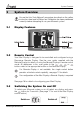
System Overview 2 System Overview Ensure that the "Auto Network" procedure described on the yellow instruction sheet and full Setup and Calibration has been performed correctly before attempting to use your Micronet system. 2.1 Display Features 2.2 Remote Control Your Maxi Display is designed to be controlled and configured using a Raymarine Remote Display. See the user guide supplied with the Remote Display for details of using the Remote Display in remote control mode.
Maxi Display 2.4 Chapter and Page operation Data is shown on the Maxi Display in Chapters, each containing several pages of related data. The diagram on page 14 shows the full set of chapters and data pages available. For a detailed description of individual data items supported on the Micronet network, see the Micronet Data user guide on your product CD or on the Raymarine web site. Selecting Chapters and Pages: Use to scroll through the chapters and between the pages within a chapter.
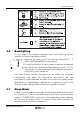
System Overview 2.6 Backlighting At any stage of the display's operation press and hold seconds to access the lighting control. for two Pressing and will scroll through setting OFF, 1, 2 and 3 whilst changing the backlighting. If using the displays at night, power usage can be reduced dramatically by switching the Backlighting to level 1 or 2. To save power, it is recommended that backlighting Level 3 is used only in dusk conditions.
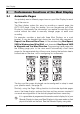
Maxi Display 3 Performance Functions of the Maxi Display 3.1 Automatic Pages You probably want a different page shown on your Maxi Display for each leg of the course. The Maxi display makes this easy by providing a special page: the AUTO LEG page. Using this feature, you can programme your Maxi Display to show exactly the information you require for each leg of the course without the need to manually change pages at each mark rounding.
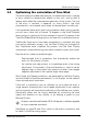
Performance Functions 3.2 Optimising the calculation of True Wind The wind angle and speed measured by a masthead wind unit is subject to error caused by aerodynamic effects on the sails, and by heel & leeway which affect the measurement geometry of the system. The size of the error is variable, it depends on many factors: the boat characteristics, wind speed, wind angle, air temperature, humidity, etc.
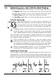
Maxi Display 3.3 Optimising your start with the Maxi Display The Maxi display provides three functions to help you get a great start: The Depart page shows your distance from the start line and how much faster (or slower) you must sail to hit the line at the start signal. The Race Timer gives you a visual and audible count down. The Line Bias page helps you choose the best position on the line.
Performance Functions The line for Depart calculations is between the positions you set. Set your points as close to the ends of the actual start line as possible. Modifying the start line points If it is necessary to modify one of the points, press while at the correct location; the popup will show that position 1 has been captured. Pressing or while the popup is visible will allow you to set the captured location to position 2. or to discard it (-). The position is captured at the moment is pressed.
Maxi Display 3.4 During the Race While racing, you are continually trimming the sails and making course adjustments in order to maximise your speed towards the next mark. It is important to know whether changes are increasing or decreasing your performance.
Performance Functions The Maxi Display automatically calculates your VMG to windward and the VMG-Wind page provides acceleration or trend arrows to help you assess the impact of changes to your course and sail trim. Wind Shift Like most things in sailing, the wind does not remain constant in either strength or direction. Every shift in the wind requires the boat to alter its heading in order to maintain a close hauled course.
Maxi Display Sailing Downwind Sailing downwind, it is rarely fastest to aim directly for the mark. Usually it is better to sail at a higher angle to increase boat speed and gybe as necessary to reach the mark. The increase in speed can more than compensate for the additional distance sailed. In technical terms, you aim to maximise your VMG (Velocity Made Good) towards the mark.
Performance Functions Drift and Set Because the boat is not always moving directly in the direction of its compass heading you need to know the direction (SET) and the speed (DRIFT) by which the boat is being pushed off course. Tactically this is important when assessing when to tack or gybe to round a mark or clear an obstruction or headland. Your Maxi Display automatically calculates this information using information from your GPS, boat speed and compass.
Maxi Display 4 Operation 4.1 Data Chapters and Pages 14 www.raymarine.
Operation 4.2 Audible Signals and Alarms At stages during its operation your Maxi Display will beep to indicate alarms or moments of importance. Power-up The display will beep once as it switches on. Button Press The display will beep once each time a button is pressed. A second beep is issued after a 2 second hold down of the button. Timer The display will beep once at each minute of the countdown. With 1 minute left to go a beep will sound every 10 seconds.
Maxi Display Wind High Alarm The wind speed has increased beyond the preset alarm level. Cross Track Error Large Alarm A large cross track error has been alerted by the GPS. Waypoint Arrival Alarm A waypoint arrival signal has been received from the GPS. The waypoint name is shown on the top line of the display. 4.3 Page Hiding When shipped from the factory a number of the less commonly used pages are hidden by default; they do not appear when you scroll through the chapters and pages.
Operation To clear Page Hiding and return to all pages visible: Press and hold to enter set up Press to reach the OPTIONS chapter Press to reach the Pages Hidden page; the display shows the total number of pages hidden Press to return to all pages visible Press and hold to exit setup. The factory reset function in setup will return page hiding to the default setting. 4.
Maxi Display 5 Setup and Calibration 5.1 Setup and Calibration Organisation Setup is organised into Chapters, each comprising a number of Pages. The Maxi Display is designed for remote control; the built in setup mode only provides settings for functions that are local to the Maxi Display. These settings are configured by operating the Maxi Display setup function in remote contol mode using a Raymarine Remote Display. See the Remote Display user guide for details of remote control mode.
Setup and Calibration 5.2 Setup and Calibration Operation To enter Setup It is not possible to enter setup mode while the Race Timer page is currently visible. Scroll to a different page in order to enter setup Press and hold , the first chapter title page is displayed. To change the active chapter Press repeatedly until the desired chapter title page is displayed. At the end of the chapter cycle, the display returns to the first chapter title page.
Maxi Display 5.4 Setup Page Descriptions Autoleg Chapter Autoleg Mode There are two modes available, SIMPLE and ADVANCD. Depending on the mode selected, the configuration pages available are as follows: Simple Mode configuration pages Start Sets the Autoleg page to be displayed while the Race Timer is counting down to the start. The default is Race Timer. Pages can be selected from any currently unhidden page.
Setup and Calibration Leg 1-2 Angle The angle at which the auto leg page switches from the Leg1 page to the Leg 2 page. The default is 60 degrees. Leg 2 Sets the autoleg page to be displayed while the apparent wind angle is between the leg 1-2 changeover angle and the leg 2-3 changeover angle. The default is True Wind Direction. Pages can be selected from any currently unhidden page. Leg 2-3 Angle The angle at which the auto leg page switches from the Leg2 page to the Leg 3 page.
Maxi Display Maximum Speed Clears the Maximum Speed memory; resets to the current speed. Average Speed Clears the Average Speed memory; resets to the current speed. Maximum True Wind Speed Resets the Maximum True Wind Speed memory; resets to the current true wind speed. Race Chapter Trends Sets the functionality of Trend or Acceleration arrows for the Speed, SOG, VMG-WIND and VMG-WP pages. The options are: OFF, ACCEL-L, ACCEL-M, ACCEL-H, TREND-L, TREND-M and TREND-H.
Setup and Calibration Boat Length Sets the length of the boat in feet. The default is 30 Feet. GPS Bow Sets the distance in feet of the GPS antenna from the bow of the boat. The default is 30 Feet.
Maxi Display RC RC Wind Speed adjustment Modifies the wind speed correction to balance readings upwind and downwind. After turning from upwind to downwind, or downwind to upwind, if the Wind Speed is now seen to be reading 1.5 knots high, apply an adjustment value of -1.5. If low, apply a + adjustment. Wind Transmitter selection Selects the type of wind transmitter installed. The options are: STANDRD and VERTICL. Do not change this setting unless you have installed a new type of Wind Transmitter.
Setup and Calibration Master Sets the capability for the Display to aquire network mastership. When set to ON the current display will seize network mastership if mastership is available. When OFF, the current display may be assigned mastership by the unit that is giving up mastership. The default is OFF. Raymarine recommend you leave this setting at OFF unless advised by www.raymarine.com.
Maxi Display 6 Seatrial and Calibration Once a Raymarine Micronet system has been installed on the vessel and Auto Networking has been completed it is necessary to carry out Calibration. It is not safe to use the displays for navigational purposes until Calibration has been carried out correctly. Accurate calibration is essential for successful use of the Maxi Display’s advanced functions.
Installation 7 Installation Your Maxi Display may be mounted on a Raymarine Mast Bracket or directly onto a bulkhead. 7.1 Bracket mounting Raymarine recommend the use of a Raymarine supplied bracket, which is designed to optimise the radio reception of the Maxi Display. Please refer to the installation instructions provided with the bracket. If using a customised bracket, you should avoid the use of conducting material (e.g Aluminium, Carbon Fibre, etc).
Maxi Display 3. Remove the four captive M4 nuts from the plastic moulding and attach the display to the mounting surface using the four self tapping screws provided. 4. Check the display is perfectly level; carefully position the button insert into the slot and snap the facia back into position. Where access is available to the rear of the mounting surface Do not bolt through from the front or replace the plastic nuts with metal nuts. This may cause the moulding to crack and will invalidate your warranty.
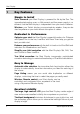
Maintenance and Fault Finding 8 Maintenance and Fault Finding 8.1 Care and Maintenance All Micronet products are totally sealed against water and are not serviceable. Any attempt to take a Micronet product apart will invalidate the warranty. To clean, use only a damp, soft cloth. No detergents, solvents or abrasives should be used. To avoid damaging a Micronet display unit we recommend storing in the supplied soft pack when not in use. If the displays are to be stored for a long period (e.g.
Maxi Display Power Save Alarm sounds There has been no significant data activity on the network. The alarm sounds to indicate that the display system will turn itself off. To continue using the system press any button to cancel the alarm. Lost Network Alarm sounds This indicates that one or more displays have lost communication with the Master. Either there is a problem with the Master display or the displays in question have been moved out of effective range.
Maintenance and Fault Finding Boat Speed reads 0 Information being transmitted from the Hull Transmitter is being received with a zero value. Check the paddle wheel for fouling, clean it and make sure it turns easily. Wind Speed reads 0 Information being transmitted from the Wind Transmitter is being received with a zero value. If the anemometer cups at the top of the mast are turning and the wind speed reads zero then there is a problem with your Wind Transmitter.
Maxi Display Specifications Height of digits: 50mm (2") Backlighting: 3 levels (optional red or amber) with daylight shutoff System-wide or local control Power: Solar Powered 300 hrs autonomy by day, 7 nights at brightest backlighting, 20 nights at economy backlighting without charge Units of display: Boat Speed (knots, km/hour, statute miles/hour) Distance (nautical miles, statute miles, kilometres) Depth (metres, feet, fathoms) Wind Speed (knots, metres per second, Beaufort) Alarm: Audible Alarms fo
www.raymarine.
Maxi Display www.raymarine.
www.raymarine.
Maxi Display This device complies with Part 15 of the FCC rules. Operation is subject to the following two conditions. (1) This device may not cause harmful interference, and (2) this device must accept any interference received, including interference’s that may cause undesirable operation. Note: the manufacturer is not responsible for any radio or TV interference caused by unauthorized modifications to this equipment. Such modifications could void the user’s authority to operate the equipment.