81304_1.
81304_1.book Page 2 Tuesday, July 31, 2007 2:44 PM Trademarks and registered trademarks Autohelm, HSB, Raymarine, Raytech, Sail Pilot, SeaTalk and Sportpilot are registered trademarks of Raymarine Limited. Apelco is a registered trademark of Raymarine Holdings Limited (Registered in all major marketing territories).
81304_1.book Page i Tuesday, July 31, 2007 2:44 PM i Contents Safety Notices........................................................1 Important information............................................3 Introduction...................................................................3 Geographic location.......................................................3 Installation..............................................................5 EMC Installation guidelines...........................................
81304_1.book Page ii Tuesday, July 31, 2007 2:44 PM ii Setting the GPS.......................................................40 Editing the satellite information................................41 Setting antenna angle and move step......................41 Antenna diagnosis...................................................42 Maintenance and troubleshooting......................43 Introduction.................................................................43 Maintenance...................................
81304_1.book Page 1 Tuesday, July 31, 2007 2:44 PM 1 Safety Notices WARNING CAUTION Product installation In-line fuse This equipment must be installed in accordance with the instructions contained in this handbook. Failure to do so may result in poor product performance, personal injury and/or damage to your boat. If you do not have a breaker in the power circuit, an inline 5 A quick blow fuse should be fitted to the positive (blue) lead of the power cable.
81304_1.
81304_1.book Page 3 Tuesday, July 31, 2007 2:44 PM 3 Important information Geographic location Introduction This handbook contains an explanation of how to install, connect and maintain your Raymarine 37STV Satellite TV System. 0 D1 6_ 57 1 Your Raymarine 37STV Satellite TV System provides uninterrupted television access to hundreds of TV channels in all types of weather conditions.
1304_1.book Page 4 Tuesday, July 31, 2007 2:44 PM 4 Raymarine 37STV Satellite TV System EMC conformance All Raymarine equipment and accessories are designed to the best industry standards for use in the leisure marine market. The design and manufacture of Raymarine equipment and accessories conform to the appropriate Electromagnetic Compatibility (EMC) standards, but correct installation is required to ensure that performance is not compromised.
81304_1.book Page 5 Tuesday, July 31, 2007 2:44 PM 5 Installation EMC Installation guidelines •More than 7ft. (2m) from the path of a radar beam. A radar beam can normally be assumed to spread 20 degrees above and below the radiating element. All Raymarine equipment and accessories are designed to the best industry standards for use in the recreational marine environment.
81304_1.book Page 6 Tuesday, July 31, 2007 2:44 PM 6 Raymarine 37STV Satellite TV System System components Raymarine STV Antenna Unit Houses the antenna positioning mechanism, low noise block (LNB), power supply and control elements within a molded radome. Connectors on the underside of the base plate join the power, signal and control cabling from the below deck units. D7945_2 Antenna Control Unit (ACU) Controls power to the antenna unit via the on/off switch.
81304_1.
81304_1.book Page 8 Tuesday, July 31, 2007 2:44 PM 8 Raymarine 37STV Satellite TV System Planning the installation 900 Make sure nearby objects do not block the antenna. It requires a +15o to +90o look angle to receive satellite signals.
81304_1.book Page 9 Tuesday, July 31, 2007 2:44 PM 9 Extending the cables The cables that have been supplied with your Raymarine Satellite TV system should be of adequate length to complete the installation on most boats. However, should it be necessary to extend a cable the following points should be considered: Power cable This cable is supplied at a length of 10 m. RF cable This cable is supplied at a length of 15 m. If a longer length is required you should replace this cable with Part No.
81304_1.book Page 10 Tuesday, July 31, 2007 2:44 PM 10 Raymarine 37STV Satellite TV System Installing the ACU ACU dimensions 227 mm (8.93 in) 217 mm (8.54 in) D10502-1 177 mm (6.97 in) 184 mm (7.25 in) 74 mm (2.
81304_1.book Page 11 Tuesday, July 31, 2007 2:44 PM 11 Installation site To install the ACU: The ACU should be installed below decks, in a position that is: 1. Select the installation site, ensuring that the proposed site meets the criteria described above. • Dry. • Well ventilated. • Easily accessible. • Near your main TV viewing area. The ACU should be installed using the two fixing brackets supplied. These brackets can be placed on the sides of the unit to provide a top or bottom fix. 2.
81304_1.book Page 12 Tuesday, July 31, 2007 2:44 PM 12 Raymarine 37STV Satellite TV System Installing the antenna Preparing the antenna Securing the antenna 1. Using a 5 mm allen key, remove the antenna dome retaining bolts and dome. Secure the antenna to the base using bolts, spring washers and flat washers. 2. Remove the foam transit restraints from the antenna base. 3. Replace and secure the antenna dome.
81304_1.book Page 13 Tuesday, July 31, 2007 2:44 PM 13 Connecting the system cables Connecting the antenna Note: It is good practice to coat the threads of all connectors with a small amount of a suitable waterproof marine sealant prior to securing them. To connect the antenna: 1. Remove the protective cap from the RF1 connector.
81304_1.book Page 14 Tuesday, July 31, 2007 2:44 PM 14 Raymarine 37STV Satellite TV System Configuring the system Your Raymarine Satellite TV system can be connected with multiple IRDs at the same time to receive pictures in different cabins offering the maximum choice of channels. In all cases the ACU must be connected to the RF1 connector of the antenna base plate. Select the set up for your area of operation from the following combinations.
81304_1.book Page 15 Tuesday, July 31, 2007 2:44 PM 15 To connect twin IRDs (Non HD): To connect twin IRDs (DirecTV HD version): 1. Connect the system as for a single IRD as described in “Single IRD” on page 14. 1. Connect an RF cable from ‘RF1’ on the antenna base plate to ‘ANT RF1’ on the ACU. 2. Remove the protective cover from the RF2 connector on the antenna base plate. 3. Connect an RF cable to the RF2 connector on the antenna base plate. 4.
81304_1.book Page 16 Tuesday, July 31, 2007 2:44 PM 16 Raymarine 37STV Satellite TV System 2. Connect ‘RF1’ on the antenna base plate to ‘ANT RF1’ of the ACU. 3. Connect an RF cable from ‘RECEIVER’ on the ACU to ‘LNB LHCP/+18V’ on the multiswitch. RF1 RF2 LNB RHCP/+13V VHF/UHF POWER LNB INPUT 24V DC LHCP/ +18V Multiswitch GROUND OUT 1 4. Connect the ‘RF2’ cable to ‘LNB RHCP/+13V’ on the multiswitch. 5.
81304_1.book Page 17 Tuesday, July 31, 2007 2:44 PM 17 6. Connect an RF cable between ‘Master IRD’ of the DiSEqC supplier and ‘Satellite’ of the Master IRD (4). RF1 7. With the system powered: • Set the ACU to ON. RF2 • The IRDs to OFF. 1 Multi-switch DiSEqC Supplier GROUND OUT 1 OUT 2 OUT 3 8. Confirm that the antenna detects and tracks the DirecTV101 satellite. 9. Set the Master IRD to ON. 10. Set the Master IRD television receiver to ON. 11. Set the remaining IRDs to ON. 12.
81304_1.book Page 18 Tuesday, July 31, 2007 2:44 PM 18 • Raymarine 37STV Satellite TV System Use the supplied PC program (This is the recommended method). Load the appropriate folder for DirecTV with multiswitch and DiSEqC supplier and follow the instructions in “Loading default satellite information using the CD-ROM” on page 39. Twin IRDs IRD 2 (not supplied) RF1 RF2 Europe The following section shows the set up combinations for Europe.
81304_1.book Page 19 Tuesday, July 31, 2007 2:44 PM 19 base plate. 4. Connect the other end of the RF cable to ‘LNB’, ‘ANT’ or ‘Satellite In’ on the rear panel of the second IRD. Full details on configuring your system IRDs will be found in the relevant Manufacturer’s handbook. RF1 RF2 Multiple IRDs IMPORTANT: Due to satellite polarization, incorrect connection in systems using multiple IRDs will result in signal degradation.
81304_1.book Page 20 Tuesday, July 31, 2007 2:44 PM 20 2. Connect the RF1 cable to ‘ANTENNA’ on the rear of the ACU. 3. Connect the RF2 cable to ‘Lo/Hor’ on the multiswitch. 4. Connect an RF cable from ‘RECEIVER’ on the rear of the ACU to ‘Lo/Ver’ on the multiswitch. 5. For each output required, connect an RF cable from an ‘OUT’ connector of the multiswitch to the ‘LNB’ or ‘ANT’ of the individual IRD units.
81304_1.book Page 21 Tuesday, July 31, 2007 2:44 PM 21 Operation Introduction Set up using the ACU This section of the handbook describes how to set up your Raymarine Satellite TV System after installation using the ACU or the Graphical User Interface (GUI) and includes the following functions: ACU soft keys The ACU soft keys are used for the following functions: BACK • System start up. • Changing the default satellite. • Monitoring the antenna status. • Entering set up mode.
81304_1.book Page 22 Tuesday, July 31, 2007 2:44 PM 22 Raymarine 37STV Satellite TV System SEARCHING A: B:HOTBIRD ASTRA 2 SETUP 3. The antenna is searching for Satellite A. Monitoring the current state of the antenna D7966_2 SEARCHING A: TRACKING A :ASTRA 2 B:HOTBIRD SETUP 4. The antenna has located the satellite and is now tracking.
81304_1.book Page 23 Tuesday, July 31, 2007 2:44 PM 23 AZ: ###.# EL:###.# SIGNAL: ### 5. Antenna position detail and signal strength is displayed. PREV Press center soft key to display NMEA GPS page. YES NEXT D7971_2 126.75E 37.20N * D10587_2 D7974_2 6. The NMEA GPS information is displayed. Press center soft key to return to antenna status display. Set up mode To enter set up mode: Setting the satellite pair The satellite pair can be changed if you change service providers.
81304_1.book Page 24 Tuesday, July 31, 2007 2:44 PM 24 Raymarine 37STV Satellite TV System 2. Set satellite A. SAT A: ASTRA2 PREV YES NEXT D10594_1 Press NEXT to show alternative satellite name. Press YES to set chosen satellite to SAT A. Press BACK to return to main set up menu or correct input errors. DiSEqC method To set the satellite pair: SET SAT PAIR ? PREV YES NEXT D7974_3 1. Follow steps 1 thru 3 for entering set up mode - see “Set up mode” on page 23. Press YES to set satellite pair.
81304_1.book Page 25 Tuesday, July 31, 2007 2:44 PM 25 4. Set satellite A when DiSEqC is active from IRD. SAT A*: DTV101 PREV YES NEXT D8644_3 5. Set satellite B when DiSEqC is active from IRD. SAT B*: DTV119 PREV YES Press NEXT or PREV to show alternative satellite name. Press YES to set chosen satellite to SAT A. Press BACK to correct input errors or return to main set up menu. NEXT D8645_3 Press NEXT or PREV to show alternative satellite name. Press YES to set chosen satellite to SAT B.
81304_1.book Page 26 Tuesday, July 31, 2007 2:44 PM 26 Raymarine 37STV Satellite TV System 4. Input the longitude data. LONGITUDE - 28.20E INPUT + D7981_2 LONGITUDE EAST 28.20E INPUT WEST + increases a value. decreases a value. Change the underscored digit using the +/- buttons. Press INPUT to accept a value. Press BACK to move to previous digit. 5. When you have input the numerical value for longitude the screen changes to enable you to select EAST or WEST. 126.75E 37.20N * D10587_2 7.
81304_1.book Page 27 Tuesday, July 31, 2007 2:44 PM 27 2. Press NEXT twice to enter Edit Sat Info mode. SET SAT PAIR ? PREV YES NEXT 6. Input satellite position. LONGITUDE - 28.20E INPUT + D7974_2 3. Press YES to enter edit mode. EDIT SAT INFO? PREV YES D7981_2 NEXT D7983_2 VER LOW 10788 - 22000 INPUT + + advances the value. - decreases the value. Change the underscored digit using the +/- buttons. Press INPUT to move to next digit.
81304_1.book Page 28 Tuesday, July 31, 2007 2:44 PM 28 Raymarine 37STV Satellite TV System HOR LOW NID 0X0020 - INPUT 10. Input the NID for Horizontal Low Band. + HOR HIGH NID 0X0020 - INPUT + D7989_2 VER HIGH 11895 27500 - INPUT + D7993_2 11. Input the tracking frequency (MHz) and symbol rate (kHz) for the Vertical High Band. 15. Select the verification VERIFY : DVB DECODE PREV SELECT NEXT D7990_2 VER HIGH NID 0X0020 - INPUT D7994_2 12. Input the NID for Vertical High Band.
81304_1.book Page 29 Tuesday, July 31, 2007 2:44 PM 29 18. Press YES to accept the data. SAVE ? YES NO Press NO to cancel and return to main set up mode. Setting the local frequency LNB systems in regions with circular polarization D7977_2 1. Press YES to enter set up mode. SET UP MODE ? YES NO 1. Verification method. SIGNAL - use only signal level for tracking. D7973_2 DVB LOCK - use only DVB Lock signal for tracking. DVB DECODE - verify satellite using DVB decode method for tracking.
81304_1.book Page 30 Tuesday, July 31, 2007 2:44 PM 30 Raymarine 37STV Satellite TV System 4. Select SINGLE LNB type. LNB TYPE : SINGLE PREV SELECT NEXT D7997_2 LOCAL FREQ: ####MHZ - INPUT + D7998_2 5. Input local frequency for the LNB. + advances the value. - decreases the value. Change the underscored digit using the +/- buttons. Press INPUT to move to next character. BACK moves to previous character. ENTER - moves to the next screen. 1. Press YES to enter set up mode.
81304_1.book Page 31 Tuesday, July 31, 2007 2:44 PM 31 5. Press YES to accept the data. SAVE ? YES NO Press NO to cancel and return to main menu. 4. Select the DiSEqC method (1) DO NOT USE DISEQC PREV SELECT . NEXT D7977_2 D8001_2 Note: Raymarine does not recommend changing the LNB type unless instructed to do so. Setting the DiSEqC method 5. Press YES to accept the selection. SAVE ? YES PREV - shows last method. SELECT - sets the displayed method. NEXT - shows next DiSEqC method.
81304_1.book Page 32 Tuesday, July 31, 2007 2:44 PM 32 Raymarine 37STV Satellite TV System 1. Press YES to enter set up mode. SET UP MODE ? YES NO ANT S/W VER : 2.95 EXIT 5. Antenna software version is shown. Press EXIT to return to main set up menu. D10589_1 D7973_2 2. Press NEXT five times to go to View Version menu. SET SAT PAIR ? PREV YES 3. Press YES to view software version. VIEW VERSION ? YES NEXT D****_1 4. Antenna product name is shown.
81304_1.book Page 33 Tuesday, July 31, 2007 2:44 PM 33 Display power 5. Antenna voltage is shown. This sequence enables you to see the power levels of the ACU, Antenna and IRDs that are installed on your system. EXIT D10591_1 1. Press YES to enter set up mode. SET UP MODE ? YES ANT POWER : 25.9V NO IRD: 18 V + ###KHZ D7973_2 EXIT YES 6. IRD voltage and frequency are shown. Press EXIT to return to main set up menu. D10592_1 2. Press NEXT six times to show View Power menu.
81304_1.book Page 34 Tuesday, July 31, 2007 2:44 PM 34 Raymarine 37STV Satellite TV System 3. Press YES to enter Ant Go Position menu. ANT GO POSITION PREV YES NEXT GO TO EL : - INPUT ###.# + D8003_2 GO TO AZ : - INPUT ###.# + D8006_2 D8007_2 4. Input required azimuth (AZ) value. + increases a value. - decreases a value. Change the underscored digit using the +/- buttons. Press INPUT to accept a value and move to next digit. Press BACK to correct input errors or return to main set up menu.
81304_1.book Page 35 Tuesday, July 31, 2007 2:44 PM 35 Setting antenna move step This sequence enables you to move the antenna in 1o steps using the ACU. 5. Move the antenna in the elevation (EL) axis. STEP EL : ###.# DOWN EXIT UP D8012_2 1. Press YES to enter set up mode. SET UP MODE ? YES NO D7973_2 2. Press NEXT nine times to show Ant Move Step menu. SET SAT PAIR ? PREV YES NEXT Setting the factory default parameters 1. Press YES to enter set up mode.
81304_1.book Page 36 Tuesday, July 31, 2007 2:44 PM 36 Raymarine 37STV Satellite TV System 3. Press YES to set default parameters.
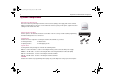
81304_1.book Page 37 Tuesday, July 31, 2007 2:44 PM 37 Set up using the Graphical User Interface You can also set up your Raymarine 37 STV Satellite TV System using the Graphical User Interface (GUI) which can be found on the CD-ROM supplied with the system.The CD-ROM contains folders for the different areas of operation. Open the folder for your area of operation and double-click the.exe icon. The GUI will appear on screen. The method of operation is the same for all versions of the GUI.
81304_1.book Page 38 Tuesday, July 31, 2007 2:44 PM 38 Raymarine 37STV Satellite TV System Controller menu The controller menu enable you to select the task that you want to carry out. Place the cursor over the required task, which will be highlighted in blue, click, and the GUI will change to show the data boxes relevant to that task. Connection status Baudrate setting Serial port setting Antenna status The antenna status information shows monitoring and set up information for your antenna. 37STV V3.
81304_1.book Page 39 Tuesday, July 31, 2007 2:44 PM 39 The GUI control soft keys View Data The following section describes the operation of the different GUI soft keys. Click this soft key to load the factory default settings into the GUI program. Update antenna Click this soft key to send the factory default settings to the antenna. Remember that this will not restart the system.
81304_1.book Page 40 Tuesday, July 31, 2007 2:44 PM 40 Raymarine 37STV Satellite TV System 5. Press ‘View Data’. A dialog box appears asking if you want to load the default settings for your region. 6. Press ‘Yes’. The satellites will now populate the buttons in the ‘Tracking Satellites ‘section. 7. Press ‘Update Antenna’. This will send the new satellite information to the antenna. 8. Press ‘Restart’ to initialize the antenna.
81304_1.book Page 41 Tuesday, July 31, 2007 2:44 PM 41 your current position. The latitude and longitude information for the selected city is displayed. 5. Click ‘Set GPS’ to save this information. 6. Click ‘Restart’. The system leaves set up mode and the antenna starts tracking. You can now change and edit the data for the selected satellite using the following command soft keys: • Register for Satellite A - registers the selected satellite as SAT A of the satellite pair.
81304_1.book Page 42 Tuesday, July 31, 2007 2:44 PM 42 Raymarine 37STV Satellite TV System To position using an absolute angle: To carry out antenna diagnosis: 1. Click ‘Move Antenna - Execute Diagnosis’ in the menu options. The move antenna screen appears. 2. Click ‘Setup’. The GUI enters set up mode. 3. Enter the azimuth (AZ) and elevation (EL) angle values in the corresponding ‘Target’ boxes of the ‘Go to position’ box. 4. Click ‘Go to Target Position’.
81304_1.book Page 43 Tuesday, July 31, 2007 2:44 PM 43 Maintenance and troubleshooting Introduction • This section deals with the maintenance and troubleshooting that can be carried out by the system user. Troubleshooting Maintenance WARNING Power supply Ensure that the system is isolated from your boat’s power supply before carrying out any maintenance. Your Raymarine Satellite TV system has been designed to require minimal maintenance.
81304_1.book Page 44 Tuesday, July 31, 2007 2:44 PM 44 Raymarine 37STV Satellite TV System installed as described in “Planning the installation” on page 8 of this handbook with regards to your radar unit. Possible cause* Symptom 1 ‘Snowy’ television picture 2 3 4 5 6 7 8 X Note: *for an explanation of the possible causes and their remedies refer to the following paragraphs. 1.
81304_1.book Page 45 Tuesday, July 31, 2007 2:44 PM 45 Antenna diagnosis 1. Press YES to enter set up mode. SET UP MODE ? YES 5. Code has been tested and passed or failed. Press EXIT to return to main set up menu. CODE 101 PASSED EXIT NO D8649_2 D7973_2 2. Press NEXT 10 times to go to Antenna Diagnosis menu. SET SAT PAIR ? PREV YES NEXT D7974_2 3. Press YES to enter diagnosis mode. ANT DIAGNOSIS ? PREV YES Code Test Code 101 Communication between antenna and ACU is being tested.
81304_1.book Page 46 Tuesday, July 31, 2007 2:44 PM 46 Raymarine 37STV Satellite TV System Technical Support You can obtain Technical Support for your Raymarine Satellite TV System from the following: www.raymarine.
81304_1.book Page 47 Tuesday, July 31, 2007 2:44 PM 47 Satellite information Introduction This section contains information on satellites in your region and includes; • Satellite coverage areas. • Satellite coverage by geographic location. • Satellite tracking information Satellite coverage areas The following satellite coverage maps do not guarantee coverage. This can be affected by climatic conditions that may cause variation in the satellite signal.
81304_1.
81304_1.
81304_1.
81304_1.
81304_1.
81304_1.
81304_1.book Page 54 Tuesday, July 31, 2007 2:44 PM 54 Raymarine 37STV Satellite TV System Satellite coverage by geographic location The following table details satellite coverage by geographic location. To receive a satellite television service other than the ‘free to air’ channels you will need to subscribe to the service from the relevant service provider. Europe Country Satellites Service provider Spain Primary: Astra - AST101GKU Hispasat www.hispasat.
81304_1.book Page 55 Tuesday, July 31, 2007 2:44 PM 55 United States Satellite Service Provider NIMIQ1 - NIM001KB NIMIQ2 - NIM002KB Bell ExpessVu www.expessvu.com Echostar 3 - ECH003KB Echostar 6.8 - ECH008KB Echostar 7 - ECH007KB Echostar 1.2 - ECH001KB Echostar Communications Corp. www.dishnetwork.com DIRECTV 2.3 - DTV123KB DIRECTV 6 - DTV006KB DirecTV Inc. www.directv.
81304_1.book Page 56 Tuesday, July 31, 2007 2:44 PM 56 Raymarine 37STV Satellite TV System Satellite tracking Your Raymarine 37STV Satellite TV System can track a variety of DVB compatible and DSS (DirecTV) satellites.Your system contains a pre-programmed library of either European or North American satellites, whichever are applicable to your system. There are also two open slots which can be programmed with user defined satellites.
81304_1.
81304_1.
81304_1.book Page 59 Tuesday, July 31, 2007 2:44 PM 59 HD information Introduction This section contains information and technical tips for using High Definition (HD) compatible satellite and television receivers with US versions of the Raymarine 37STV Satellite TV System. Satellite switching The satellite receiver has the ability to switch satellites automatically using a DiSEqC signal. As you change channels on the television, the receiver will send a DiSEqC signal when another satellite is required.
81304_1.book Page 60 Tuesday, July 31, 2007 2:44 PM 60 pairs. you will have to carry out a manual soft key press during this section of the set up procedure. The test will check for DTV101 and you will get an OK. It will then check for DTV119, and you will again get an OK. As it begins searching for DTV110# you will have to manually press the SAT B pair on the ACU. The receiver will then be able to locate DTV110#. 4. Once set up is complete, the receiver will start downloading the guide.
81304_1.book Page 61 Tuesday, July 31, 2007 2:44 PM 61 Technical specification General Approvals CE - conforms to FCC - verified to Dimensions Antenna Antenna dish Antenna Control Unit Weight Antenna Antenna Control Unit Environmental Operating temperature range Storage temperature range Humidity limits Antenna system performance Frequency Ku Band 10.7 to 12.75 GHz Minimum EIRP 50 dBW Azimuth range 680o Elevation range +10o ~ +80o EU Directive 89/336/EEC CFR:47: Part 15 43 cm(16.
81304_1.