87075_2.
87075_2.book Page 2 Thursday, November 22, 2007 8:07 AM SeaTalk is a registered trademark of Raymarine Ltd.
87075_2.book Page i Thursday, November 22, 2007 8:07 AM i Contents Preface ............................................................................................................................v Safety notices .......................................................................................................... v EMC Conformance .................................................................................................. v Limitations on pressure washing ....................................
87075_2.book Page ii Thursday, November 22, 2007 8:07 AM ii SPX-5 Pilot Series Operating Guide 2.5 Adapting the installation ............................................................................... 16 Pushrod extension........................................................................................ 16 Pushrod mounting ........................................................................................ 16 Cantilever socket .................................................................
87075_2.book Page iii Thursday, November 22, 2007 8:07 AM Contents iii Compass calibration ................................................................................. 35 Swinging the compass ............................................................................ 35 Aligning the compass heading ................................................................ 37 AutoLearn ................................................................................................. 38 Commissioning complete .
87075_2.book Page iv Thursday, November 22, 2007 8:07 AM iv SPX-5 Pilot Series Operating Guide AutoTack angle ............................................................................................. 55 Gybe inhibit................................................................................................... 56 Wind selection .............................................................................................. 56 WindTrim .................................................................
87075_2.book Page v Thursday, November 22, 2007 8:07 AM Preface v Preface Contents Safety notices WARNING: Product installation & operation This equipment must be installed, commissioned and operated in accordance with the Raymarine instructions provided. Failure to do so could result in personal injury, damage to your boat and/or poor product performance. WARNING: Switch off power supply Make sure you have switched off the power supply before you start installing this product.
7075_2.book Page vi Thursday, November 22, 2007 8:07 AM vi SmartPilot X-5 Tiller & GP Tiller Installation & Setup Guide Product documents This document is part of a series of books associated with the SPX-5 Tiller system. Documents can be downloaded from www.raymarine.com/handbooks.
87075_2.book Page 1 Thursday, November 22, 2007 8:07 AM 1 Chapter 1: Installation and system overviews This chapter gives an overview of installation procedures and network configurations for an SPX-5 Tiller system. 1.1 Installation overview There are two stages to installing an SPX-5 Tiller system, namely planning the installation, then installing and mounting the components.
87075_2.book Page 2 Thursday, November 22, 2007 8:07 AM 2 SmartPilot X-5 Tiller & GP Tiller Installation & Setup Guide 1.3 System overviews The SPX-5 Tiller system consists of a number of components connected together using a Raymarine SeaTalk bus. SPX-5 Tiller system - key components Course Computer Drive unit ST6002 Pilot Controller Fluxgate compass D10510-1 Marine electronics systems The autopilot may form part of your wider ships electronics system.
87075_2.book Page 3 Thursday, November 22, 2007 8:07 AM Chapter 1: Installation and system overviews 3 Example SeaTalk system SeaTalk allows connection of compatible instruments and equipment though a dedicated data bus. This allows information sharing around the ships electronics system.
87075_2.book Page 4 Thursday, November 22, 2007 8:07 AM 4 SmartPilot X-5 Tiller & GP Tiller Installation & Setup Guide 1.4 Equipment & Tools Before you begin ensure you have all the necessary components and tools to install your system.
87075_2.book Page 5 Thursday, November 22, 2007 8:07 AM Chapter 1: Installation and system overviews Tools and equipment NOT supplied You will need to supply the following equipment and tools: Tools: • Drill • 2.5 mm (3/32"), 6 mm(1/4"), 12.5 mm (1/2"), 18 mm (23/32") drill bits • Two-part epoxy (Araldite) adhesive • Cross-head/pozi-drive screwdriver • Slotted-head screwdriver Cables / equipment • Power cable and fuse/breaker. See page 19. • Additional data cables (e.g.
87075_2.book Page 6 Thursday, November 22, 2007 8:07 AM 6 SmartPilot X-5 Tiller & GP Tiller Installation & Setup Guide Part Number Description D029 Pedestal Socket 76 mm (3") D030 Pedestal Socket 89 mm (3.5") D031 Cantilever Socket D159 Tiller Bracket 102 mm (4") D160 Tiller Bracket 127 mm (5") 1.5 Create a schematic diagram As part of the preparation for installing your SPX-5 Tiller system, we recommend that you create a schematic diagram representing the system you want to install.
87075_2.book Page 7 Thursday, November 22, 2007 8:07 AM 7 Chapter 2: Installing the system Before proceeding with the installation you should have the following to hand: • All necessary equipment and tools to install your SPX-5 Tiller system.. • The correct type and length of power cable. • Schematic diagram detailing autopilot system location and connections. You should also check that existing marine electronics, such as the GPS are installed and working. 2.
87075_2.book Page 8 Thursday, November 22, 2007 8:07 AM 8 SmartPilot X-5 Tiller & GP Tiller Installation & Setup Guide Suppression ferrites Raymarine cables may be fitted with suppression ferrites. These are important for correct EMC performance. Any ferrite removed to facilitate installation must be replaced in the original position immediately after the installation is complete. • Use only ferrites of the correct type, supplied by Raymarine authorized dealers.
87075_2.book Page 9 Thursday, November 22, 2007 8:07 AM Chapter 2: Installing the system 9 CAUTION: Power cable Using an incorrect size of power cable could reduce the power supplied to the drive unit and therefore cause your SPX-5 Tiller system to malfunction. Ensure the correct cable size is used. If in doubt, use a heavier gauge cable. The requirement for power cables depends on the total length of the power circuit. That is the total length of Cable A + Cable B + Cable C.
87075_2.book Page 10 Thursday, November 22, 2007 8:07 AM SmartPilot X-5 Tiller & GP Tiller Installation & Setup Guide M VE OUN RT T ICA LLY 170 mm (6.7 in) 10 237 mm (9.33 in) 56 mm (2.
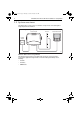
87075_2.book Page 11 Thursday, November 22, 2007 8:07 AM Chapter 2: Installing the system 11 X-5 connection overview The X-5 course computer provides the following system connections. SeaTalk fuse (2 A) Power fuse (10 A) 2 10 Note: Spare fuses are located in the connector cover A Fluxgate compass inputs NMEA 0183 input/ouput Rudder position sensor inputs SeaTalk inputs/outputs SeaTalkng inputs/outputs Power inputs (12 V) B RF ground connection Drive motor outputs D10374-1 2.
87075_2.book Page 12 Thursday, November 22, 2007 8:07 AM 12 SmartPilot X-5 Tiller & GP Tiller Installation & Setup Guide Use the following table to determine the required position for your vessel.
87075_2.book Page 13 Thursday, November 22, 2007 8:07 AM Chapter 2: Installing the system 13 If you need to adapt the standard installation, refer to Adapting the installation on page 16 for adaptation options. Step 1 - Mount the Tiller Drive Use this procedure when neither accessories or adaptation of the drive unit position are required. 1. Securely clamp the tiller, mark the pin position and drill the 6 mm (1/4”) hole. 2. Fix the pin in position using a two-part epoxy adhesive. 3.
87075_2.book Page 14 Thursday, November 22, 2007 8:07 AM 14 SmartPilot X-5 Tiller & GP Tiller Installation & Setup Guide . 4. nA 620 m sio m (24 n me Di .5 in) 12.5 mm (1/2 in) 25mm (1.0 in) 5. D10706-1 6.
87075_2.book Page 15 Thursday, November 22, 2007 8:07 AM Chapter 2: Installing the system 15 Step 2 - Install the socket Cable requirement CAUTION: Power cable Using an incorrect size of power cable could cause your SPX-5 Tiller system to malfunction and reduce the power supplied to the drive unit. Ensure the correct size is used. If in doubt, use a heavier gauge cable.
87075_2.book Page 16 Thursday, November 22, 2007 8:07 AM 16 SmartPilot X-5 Tiller & GP Tiller Installation & Setup Guide 2.5 Adapting the installation Note: Refer to Accessories on page 5 for details of parts available to adapt your installation. Pushrod extension Referring to the following illustration, if dimension C is greater than 620 mm (24.5”), use a pushrod extension. C D10652-1 L To use a pushrod extension: 1. Select a pushrod extension with a length L nearest to C - 620 mm (24.5”). 2.
87075_2.book Page 17 Thursday, November 22, 2007 8:07 AM Chapter 2: Installing the system 17 To use the cantilever socket: 1. Use a hacksaw to cut the rod to length L = F - 635 mm (25”). 2. Assemble the mounting ring, rod and socket. 3. With the drive horizontal mark the location of the mounting ring and its holes. 4. Drill three 6 mm (1/4”) diameter clearance holes at the marked positions. 5. Apply a thin coat of silicone sealant to the base of the mounting ring. 6.
87075_2.book Page 18 Thursday, November 22, 2007 8:07 AM 18 SmartPilot X-5 Tiller & GP Tiller Installation & Setup Guide Tiller brackets If the tiller is higher or lower than the mounting socket, use a tiller bracket to vary the tiller pin height so the drive is horizontal. D8813_1 D D8814_1 E If the drive is below the tiller, bracket size equals dimension D. If the drive is above the tiller; bracket size equals dimension E - 25 mm (1”). To use a tiller bracket: 1.
87075_2.book Page 19 Thursday, November 22, 2007 8:07 AM Chapter 2: Installing the system 19 3. Drill two 6 mm (1/4”) diameter clearance holes through the center line of the tiller at the positions marked. 4. Attach the tiller bracket using two 6 mm (1/4“) diameter bolts, nuts and washers. 5. Fix the bolts in position using two-part epoxy adhesive. 6. When the epoxy is completely hardened, fully tighten the nuts. m 7m (18 in) 45 D8815_2 90 degrees 2.
87075_2.book Page 20 Thursday, November 22, 2007 8:07 AM 20 SmartPilot X-5 Tiller & GP Tiller Installation & Setup Guide Connection procedure A Brown Red B Blue Black Distribution panel Drive unit Fuse or circuit breaker Power supply D10622-1 At the Course Computer, locate the free ends of the power cable from the distribution panel and Tiller Drive cable.
87075_2.book Page 21 Thursday, November 22, 2007 8:07 AM Chapter 2: Installing the system 21 2.7 Fluxgate compass Note: If you intend using a separate NMEA compass, do not connect the Fluxgate Compass supplied with your X-5 Tiller system. Instead, connect the NMEA compass to the NMEA input on the SPX-5 Tiller system. Use these instructions to install the Fluxgate Compass. After fitting the Fluxgate Compass, ensure you affix the compass safe area label adjacent to the Fluxgate Compass.
87075_2.book Page 22 Thursday, November 22, 2007 8:07 AM 22 SmartPilot X-5 Tiller & GP Tiller Installation & Setup Guide Ver tica l D10618-1 Compass connection Route the compass cable to the Course Computer, securing it at regular intervals with suitable cable clips/ties. Connect to the Course Computer as in the following illustration.
87075_2.book Page 23 Thursday, November 22, 2007 8:07 AM Chapter 2: Installing the system 23 2.8 Pilot Controller Fitting The ST6002 Pilot Controller is supplied with an 9 m cable for connection to the SeaTalk bus. Ensure that your mounting location is within 9 m of a suitable connection point. You may purchase a longer cable if required. Fit the controller in accordance with the separate instruction leaflet.
87075_2.
87075_2.book Page 25 Thursday, November 22, 2007 8:07 AM Chapter 2: Installing the system 25 2.9 Connect to ground CAUTION: Grounding SPX-5 Tiller system ground MUST be connected to ship’s ground. Failure to connect to ship’s ground may cause it, or other on-board electronics to malfunction. To ground your SPX-5 Tiller system: • Use a dedicated earthing plate (e.g. dynaplate) in contact with the water. • Use flat tinned copper braid, 30 A rating (1/4 inch) or greater.
87075_2.book Page 26 Thursday, November 22, 2007 8:07 AM 26 SmartPilot X-5 Tiller & GP Tiller Installation & Setup Guide 2.10Optional connections Rudder reference An optional rudder reference transducer is available to provide an accurate display of the rudder angle. If you have the optional rudder reference transducer, connect it to the course computer as shown.
87075_2.book Page 27 Thursday, November 22, 2007 8:07 AM Chapter 2: Installing the system 27 SeaTalkng Connections To connect your autopilot to a SeaTalkng backbone, use a dedicated spur cable.
87075_2.book Page 28 Thursday, November 22, 2007 8:07 AM 28 SmartPilot X-5 Tiller & GP Tiller Installation & Setup Guide NMEA 0183 equipment The SPX-5 Tiller system can connect to NMEA devices such as a GPS or chartplotter. +ve IN -ve IN +ve OUT -ve OUT +ve OUT -ve OUT +ve IN -ve IN Screen not connected NMEA DEVICE D10539-1 Data bridging The SPX-5 Tiller system acts as a bridge between SeaTalk and NMEA, allowing NMEA and SeaTalk devices to share information.
87075_2.book Page 29 Thursday, November 22, 2007 8:07 AM Chapter 2: Installing the system 29 2.11Final checks When you have completed all necessary installation procedures, but before you apply power to the system, ensure all equipment and connections are properly secured. Secure all cables To prevent strain on the connector blocks, secure the cables to the Course Computer with cable ties as shown below. D10396-1 2.
87075_2.
87075_2.book Page 31 Thursday, November 22, 2007 8:07 AM 31 Chapter 3: Commissioning & setup This chapter describes the commissioning and setup procedures for your Raymarine SPX-5 Tiller system. Requirement The commissioning procedures are mandatory and must be carried out after installation, before the SPX-5 Tiller system is used to steer the boat. Additional setup procedures are also provided for you to fine tune your SPX-5 Tiller system for optimum performance with your boat.
87075_2.book Page 32 Thursday, November 22, 2007 8:07 AM 32 SmartPilot X-5 Tiller & GP Tiller Installation & Setup Guide TRUE D10524-1 Check SeaTalk and NMEA 0183 connections SeaTalk instruments If you have connected the Pilot Controller to other SeaTalk instruments or controllers: 1. Select display lighting level 3 (LAMP 3) on one of the other SeaTalk instruments or controllers. 2. Check that the Pilot Controller display lights are on.
87075_2.book Page 33 Thursday, November 22, 2007 8:07 AM Chapter 3: Commissioning & setup 33 D10646-1 4. If the rudder moves to port or the rudder drives hard over: i. Press standby. ii. Turn off the power. iii. Reverse the motor wires connected to the SPX-5 Tiller system computer. iv. Switch on the power and re-check. Note: If the rudder overshoots and has to drive back or starts to hunt back and forth, increase the rudder damping level manually (See page 54).
87075_2.book Page 34 Thursday, November 22, 2007 8:07 AM 34 SmartPilot X-5 Tiller & GP Tiller Installation & Setup Guide Set the vessel type When you select a vessel type, the SPX-5 Tiller system automatically selects appropriate default values for various other calibration settings. These default values are listed on page 58. To setup the vessel type, enter Dealer calibration then: 1.
87075_2.book Page 35 Thursday, November 22, 2007 8:07 AM Chapter 3: Commissioning & setup 35 Save the new settings When you have adjusted the above settings hold down standby for two seconds, to save your changes, leave Dealer calibration and return to the Standby mode. Seatrial calibration When you have completed the dockside checks, carry out a Seatrial calibration, to calibrate the compass and set up the autopilot steering characteristics.
87075_2.book Page 36 Thursday, November 22, 2007 8:07 AM 36 SmartPilot X-5 Tiller & GP Tiller Installation & Setup Guide 2. Use disp to move through the Seatrial calibration items until you see SWING COMPASS. 2 sec x2 D10541-1 Note: If you cannot access Seatrial calibration, you need to disable the calibration lock. This can be found in Dealer calibration (see page 52). 3. When you are ready to start, press +1, to select SWING COMPASS ON. 4. Press auto to start the compass swing.
87075_2.book Page 37 Thursday, November 22, 2007 8:07 AM Chapter 3: Commissioning & setup 37 Aligning the compass heading Once the deviation is displayed, press disp to move to the Heading Alignment (ALIGN HDG) page, then: 1. Manually steer the boat on a steady course at a speed sufficient to hold the course. 2. If you have a GPS connected to your SPX-5 Tiller system: i. Increase the boat speed to more than 3 knots ii. Press auto.
87075_2.book Page 38 Thursday, November 22, 2007 8:07 AM 38 SmartPilot X-5 Tiller & GP Tiller Installation & Setup Guide AutoLearn WARNING: Ensure there is enough clear sea space The AutoLearn process takes the boat through a number of maneuvers, which can result in sudden, sharp turns, especially when the AutoLearn function is run on more maneuverable boats. Therefore, ensure there is a significant amount of CLEAR SEA SPACE in front of the boat, before starting an AutoLearn process.
87075_2.book Page 39 Thursday, November 22, 2007 8:07 AM Chapter 3: Commissioning & setup 39 Enter Seatrial calibration 2 sec x2 Prepare for AutoLearn • steer straight ahead at cruising speed (planing boats – just on the plane) • head into wind and waves x4 CHECK! Before proceeding, ensure you have sufficient clear sea space Start AutoLearn AutoLearn in progress D10545-1 5. The screen will show the CLEAR TO MANEUVER message.
87075_2.
87075_2.book Page 41 Thursday, November 22, 2007 8:07 AM Chapter 3: Commissioning & setup 41 Over time you may wish to repeat these adjustments using a range of sea conditions and headings to achieve optimum all-round performance for your particular vessel and preferences. Adjust these settings when motoring your boat at cruising speed. Response level The principal method of adjusting the performance of an SPX-5 Tiller system is by changing the response level.
87075_2.book Page 42 Thursday, November 22, 2007 8:07 AM 42 SmartPilot X-5 Tiller & GP Tiller Installation & Setup Guide • If the rudder gain is too low, the boat’s performance will be sluggish – it will take a long time to make the 40° turn and there will be no overshoot (B). Correct this understeer by increasing the rudder gain setting. New heading B New heading A Rudder gain too low New heading Rudder gain too high Correct rudder gain D3262-3 To adjust the rudder gain: 1.
87075_2.book Page 43 Thursday, November 22, 2007 8:07 AM Chapter 3: Commissioning & setup 43 3. Press and hold standby for 2 seconds to save the changes. 4. Press auto to check the SPX-5 Tiller system performance in Auto mode. AutoTrim You may also wish to adjust the AutoTrim setting. AutoTrim determines how quickly the SPX-5 Tiller system applies ‘standing helm’ to correct for trim changes, caused, for example, by changes in the wind load on the superstructure, or an imbalance of engines.
87075_2.
87075_2.book Page 45 Thursday, November 22, 2007 8:07 AM 45 Chapter 4: SPX-5 Tiller system settings 4.1 Introduction This chapter describes the SPX-5 Tiller system calibration settings and the factory default settings. The calibration settings can be adjusted to best suit your operating requirements, but as many will have been adjusted to optimum values when commissioning the system, they should not require further change.
87075_2.book Page 46 Thursday, November 22, 2007 8:07 AM 46 SmartPilot X-5 Tiller & GP Tiller Installation & Setup Guide Accessing the Calibration modes Accessing Calibration Modes 2 seconds 2 seconds (saves changes) Calibration Modes to enter display calibration mode to enter user calibration mode to enter seatrial calibration mode CAL ? + to enter dealer calibration mode D10647-1 Adjusting calibration values To adjust calibration values; 1.
87075_2.book Page 47 Thursday, November 22, 2007 8:07 AM Chapter 4: SPX-5 Tiller system settings 47 4.2 Display calibration Display calibration provides settings to adjust the information displayed on the Pilot Controller.
87075_2.
87075_2.book Page 49 Thursday, November 22, 2007 8:07 AM Chapter 4: SPX-5 Tiller system settings 49 Available Data Pages Displayed as Bearing to Waypoint BTW Rudder Gain RUDD GAIN Response RESPONSE Watch WATCH - used to control the Watch timer Universal Time Coordinated UTC Note: There are 3 depth pages (meters, feet and fathoms) and 2 water temperature pages (°C and °F). The SPX-5 Tiller system will display the depth data or water temperature in the units defined by data page you select.
87075_2.book Page 50 Thursday, November 22, 2007 8:07 AM 50 SmartPilot X-5 Tiller & GP Tiller Installation & Setup Guide AutoTack Use this screen to select how the vessel performs when using AutoTack. You can either: • Set a default AutoTack angle. This is the angle through which the boat will turn when an AutoTack is performed. or • Select Relative Tack operation.
87075_2.book Page 51 Thursday, November 22, 2007 8:07 AM Chapter 4: SPX-5 Tiller system settings 51 WindTrim WindTrim controls how quickly the SPX-5 Tiller system responds to changes in the wind direction. Higher wind trim settings will result in a system that is more responsive to wind changes.
87075_2.book Page 52 Thursday, November 22, 2007 8:07 AM 52 SmartPilot X-5 Tiller & GP Tiller Installation & Setup Guide Accessing Dealer Calibration + 2 seconds (saves changes) Dealer Calibration To adjust values or or To exit & save changes 2 seconds D10603-1 Seatrial calibration lock This screen controls the access to Seatrial calibration.
87075_2.book Page 53 Thursday, November 22, 2007 8:07 AM Chapter 4: SPX-5 Tiller system settings 53 The correct setting for the SPX-5 Tiller system is SAIL BOAT. This should be set when commissioning the SPX-5 Tiller system. Drive type The drive type setting controls how the SPX-5 Tiller system drives the steering system. The correct setting for the SPX-5 Tiller system is 3.This should be set when commissioning the SPX-5 Tiller system.
87075_2.book Page 54 Thursday, November 22, 2007 8:07 AM 54 SmartPilot X-5 Tiller & GP Tiller Installation & Setup Guide The default counter rudder gain is set during the initial seatrial, as part of the AutoLearn process (see page 42). Screen Text Range COUNT RUD 1 to 9 (Do NOT set to 0) Rudder damping If the SPX-5 Tiller system ‘hunts’ when trying to position the rudder, adjust the rudder damping value to minimize this. Increasing the rudder damping value reduces hunting.
87075_2.book Page 55 Thursday, November 22, 2007 8:07 AM Chapter 4: SPX-5 Tiller system settings 55 Screen Text Options RESPONSE Range = 1 to 9 Level 1 to 3 minimizes the amount of pilot activity. This conserves power, but may compromise short-term course-keeping accuracy Level 4 to 6 should give good course keeping with crisp, well controlled turns under normal operating conditions Level 7 to 9 gives the tightest course keeping and greatest rudder activity (and power consumption).
87075_2.book Page 56 Thursday, November 22, 2007 8:07 AM 56 SmartPilot X-5 Tiller & GP Tiller Installation & Setup Guide . Screen Text Options AUTO TACK 40° to 125° in 1° steps Gybe inhibit With gybe inhibit on: • You will be able to perform an AutoTack into the wind • The SPX-5 Tiller system will prevent the boat from performing an AutoTack away from the wind With gybe inhibit off, you can perform an AutoTack into or away from the wind. .
87075_2.book Page 57 Thursday, November 22, 2007 8:07 AM Chapter 4: SPX-5 Tiller system settings 57 . Options OFF Joystick off 1 1 = Proportional power steer Proportional power steer applies rudder in proportion to joystick movement – the further the joystick is held over, the greater the applied rudder.
87075_2.book Page 58 Thursday, November 22, 2007 8:07 AM 58 SmartPilot X-5 Tiller & GP Tiller Installation & Setup Guide To carry out a system reset: 1. Select the System reset (RESET) screen in Dealer calibration. 2. Press +1 then press AUTO. 3. The screen will then show an ARE YOU SURE message: • Press auto to cancel the reset or • Press +1 again to select YES and reset the SPX-5 Tiller system. 4.
87075_2.book Page 59 Thursday, November 22, 2007 8:07 AM 59 Appendix 1: NMEA 0183 sentences The SPX-5 Tiller Course Computer computer supports the following NMEA0183 sentences.
87075_2.
87075_2.
87075_2.
87075_2.book Page 63 Thursday, November 22, 2007 8:07 AM SPX-5 Tiller system specifications 63 Pilot Controller (ST6002) Nominal supply voltage: 12 V DC via SeaTalk Operating voltage range: 10 V to 15 V DC Current consumption (in Standby mode) 60 mA (less than 200 mA with full lighting) Operating temperature: 0 °C to +70 °C (32 °F to 158 °F) Water protection: waterproof to CFR46 Overall dimensions: width height depth 110 mm (4.33 in) 115 mm (4.53 in) 41 mm (1.
87075_2.
87075_2.
87075_2.
87075_2.book Page 67 Thursday, November 22, 2007 8:07 AM Tiller Drive socket template Drill 2.
87075_2.