
Setup guide

Chapter 2: Installing the system 11
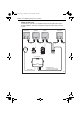
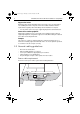
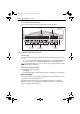
X-5 connection overview
The X-5 course computer provides the following system connections.
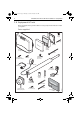
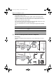
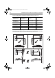
2.4 Install the Tiller Drive
Drive type
The correct Tiller drive unit type is dependent on the fully laden displacement of the
vessel.
• For vessels up to 6 tonnes fully laden displacement, use the standard tiller drive.
• For vessels up to 7.5 tonnes fully laden displacement, use the GP tiller drive.
Note:
The actual laden displacement for a vessel can be up to 20% greater than the manufac-
turer’s published displacement figures.
Mounting requirements
The Tiller Drive must be mounted:
• Horizontally
• So that when the tiller is centered, the drive axis is at 90 degrees to the tiller axis.
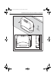
Drive unit position
The tiller pin and drive socket can be mounted between 356 mm and 457 mm (14” -
18”) from the centre of the rudder stock.
For quicker rudder response in vessels requiring faster turn rates (e.g. lighter
displacement vessels), install the tiller pin and drive pedestal closer to the rudder
stock, to a minimum of 356 mm (14").
102
A B
Fluxgate
compass inputs
Rudder position
sensor inputs
SeaTalk
inputs/outputs
Power
inputs
(12 V)
RF ground
connection
NMEA 0183
input/ouput
SeaTalk
ng
inputs/outputs
Drive motor
outputs
D10374-1
SeaTalk fuse
(2 A)
Power fuse
(10 A)
Note: Spare fuses
are located in the
connector cover
87075_2.book Page 11 Thursday, November 22, 2007 8:07 AM