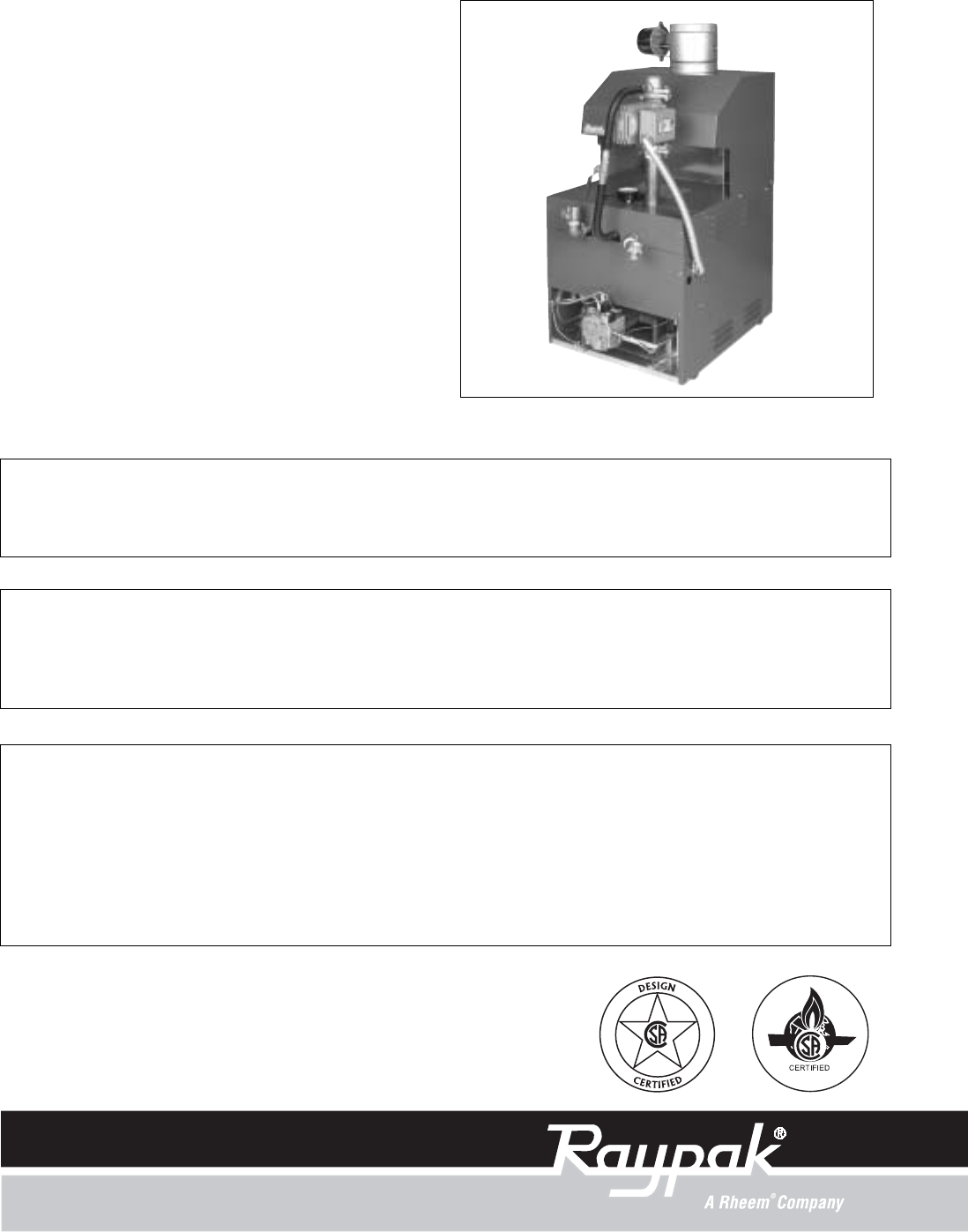
INSTALLATION AND OPERATING INSTRUCTIONS Catalog No.: 2100.50V Effective: 04-01-04 Replaces: 01-01-03 RaythermTM Type H RESIDENTIAL BOILERS Models 0030B, 0042B, 0066B,0090B 0135B, 0180B FOR YOUR SAFETY Do not store or use gasoline or other flammable vapors and liquids or other combustible materials in the vicinity of this or any other appliance. To do so may result in an explosion or fire.
Contents RECEIVING EQUIPMENT................................................................................. 3 GENERAL SPECIFICATIONS........................................................................... 3 INSTALLATION PROCEDURES........................................................................ 4 Code Requirements..................................................................................... 4 Mounting Base....................................................................................
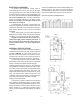
RECEIVING EQUIPMENT Follow the installation instructions furnished with the vent damper package. The plug-in connector can also be used with power venters. Refer to the specific installation instructions supplied by the power vent manufacturer. On receipt of your equipment, visually check for external damage to the carton. If the carton is damaged, it is suggested that a note be made on the Bill of Lading when signing for the equipment.
3. INSTALLATION PROCEDURES CODE REQUIREMENTS Installation must be in accordance with local codes, or, in the absence of local codes, with the latest editions of the National Fuel Gas Code, ANSI Z223.1, and the National Electrical Code, ANSI/NFPA 70. In Canada, installations must conform with the current CAN/CGA B149.1 or .2 and the Canadian Electrical Code Part 1 CSA C22.2 No.1.
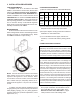
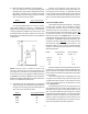
2) When the boiler is installed in a confined space such as a utility room or closet (Models 0030,0042 and 0066 only), where all air is supplied from inside the building, the boiler room must be provided with two openings, each one having a minimum net free area, in square inches as follows: Model 0030, 0042 & 0066 Location of the openings is the same as in the previous case - that is, within 12" of the top, and within 12" of the bottom of the enclosure.
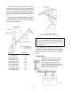
The weight of the vent stack or chimney must not rest on the boiler's drafthood. Support must be provided in compliance with applicable codes. The boiler top and drafthood must be readily removable for maintenance and inspection. Vent pipe should be adequately supported to maintain proper clearances from combustible construction. Type "B" double-wall (or equivalent vent pipe is recommended.
At the time of removal of an existing boiler, the following steps shall be followed with each appliance remaining connected to the common venting system placed in operation, while the other appliances remaining connected to the common venting system are not in operation. VENT DAMPER INSTALLATION LOCATION The vent damper supplied with each boiler must be located in the vent so that it serves only the appliance for which it is intended.
MOUNTING On vertical vents, the vent damper may be mounted with the actuator in any position. On horizontal vents, do not mount the actuator either directly above or directly below the vent pipe; mount the vent damper actuator to the side of the vent. The vent damper is set up for a continuous pilot system.
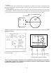
VENT DAMPER OPERATION For safe, efficient operation, the vent damper and all flue-product-carrying areas of the appliance must be checked annually, with particular attention given to deterioration from corrosion or other sources. Check vent damper operation as follows: 1. When the boiler is off, check that the vent damper position indicator points to the closed position, below.
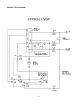
CONNECTION DIAGRAM 10
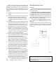
GAS SUPPLY CONNECTIONS The inlet gas connection of the boiler gas valve is 1/2". Provide an adequate gas piping supply line no smaller than 1/2", according to the chart below: The gas valve is provided with pressure taps to measure gas pressure upstream of the gas valve and downstream which is the same as the manifold pressure. Maximum Equivalent Pipe Length (Feet) WATER CONNECTIONS & SYSTEM PIPING The pipe size for water connections is shown on page 3. Typical piping systems are shown on pages 12 to 14.
Systems with multiple zones may require an additional circulator. Consult manufacturer's data for valve pressure drops. When an indirect water heating system is used, it is recommended that a separate circulator be installed to meet the required flow and pressure drop conditions of the indirect water heater. We recommend that the make-up water from the cold water line have a check valve, gate valve, and feedwater regulator set at 12 psig.
AIR VENT AIR SCOOP FEED VALVE DIAPHRAGM EXPANSION TANK PIPEPRESSURE RELIEF VALVE TO DRAIN ZONE VALVES COLD WATER INLET HOT WATER SUPPLY HEATING UNITS CIRCULATOR COLD WATER SUPPLY Fig.# 8998.
AIR VENT 12" MAX. AIR SCOOP FEED VALVE DIAPHRAGM EXPANSION TANK PIPE PRESSURE RELIEF VALVE TO DRAIN CIRCULATORS COLD WATER INLET HEATING UNITS Fig. #8999.1 MULTIPLE ZONES WITH CIRCULATORS AIR VENT AIR SCOOP FEED VALVE DIAPHRAGM EXPANSION TANK PIPE PRESSURE RELIEF VALVE TO DRAIN COLD WATER INLET ZONE VALVES HEATING UNITS Fig. #9000.
ELECTRICAL WIRING The electrical power supply requirement for these boilers is 115 volts, 60 Hz. Field wiring connections and electrical grounding must comply with the local codes, or in the absence of local codes, with the National Electrical Code, ANSI/NFPA 70-1987. Provide a separate fused circuit from the main electrical panel to the boiler, and a disconnecting means within sight of the boiler. Remove the control box cover and make the power supply connections in the field wiring compartment.
WIRING DIAGRAM KEY 16
WIRING DIAGRAM: Single-Zone Taco Valve Fig. # 2228e WIRING DIAGRAM: Dual-Zone Taco Valve Fig. # 2229e NOTE: Maximum three (3) zone valves per one (1) 40 VA transformer. WIRING DIAGRAM: Dual-Zone Honeywell Valve Fig. # 2230e NOTE: Maximum five (5) zone valves per one (1) 40 VA Transformer.
WIRING DIAGRAM: System with (3) Zone Pumps Fig. #2232e NOTE: Check VA rating of each relay coil. Total load must not exceed VA rating of transformer. WIRING DIAGRAM: Power Vent System w/ Zone Valve Fig. #2233e Fig.
WIRING DIAGRAM: Primary/Secondary Pumping System Honeywell Zone Valve Fig. #2223.
WIRING DIAGRAM: Standing Pilot With Low Water Cut-off Device Fig. # 2223.1e Note: Low water cut-off (LWCO) and system switch supplied by others. WIRING DIAGRAM: IID Units With Low Water Cut-off Device Fig. # 2357E Note: Low water cut-off (LWCO) and system switch supplied by others.
4. SERVICING PROCEDURES GENERAL LOCATION OF CONTROLS CIRCULATOR VENT SENSOR CONTROL BOX COMPONENT LOCATIONS MODELS 135 & 180 2-Stage Controller BYPASS VALVE (MODELS 135 & 180 ONLY) BYPASS LINE TEMPERATURE AND PRESSURE GAUGE Relay 2-STAGED CONTROLLER (MODEL 90 ONLY) PRESSURE RELIEF VALVE RELAY ADJUSTABLE HIGH LIMIT FIELD WIRING COMPARTMENT FastIgnition Module Response Temperature (Auto Ignition Only) Sensor Fig.# 8195.
START-UP PROCEDURES Filling the System Fill system with water. Purge all air from the system using purge valve sequence. After system is purged of air, lower system pressure. Open valves for normal system operation, fill system through feed pressure regulator to minimum 12 PSI. Manually open air vent on the compression tank until water appears, then close vent. On multiple-zone systems, purge each zone separately. Isolate the other zones while one zone is being purged of air.
10. Turn on all electrical power to the boiler. 11. Set the thermostat to the desired setting. FOR STANDING PILOT MODELS WITH ROBERTSHAW GAS VALVE, 2-STAGE OPERATION (Models 90, 135 & 180) 1. 2. 3. 4. TO TURN OFF GAS TO THE BOILER: (Models 90, 135 & 180) STOP! Read the safety information. Set the thermostat to the lowest setting. Turn off all electrical power to the boiler. Push in and move gas control lever counterclockwise to "OFF" position. 1. Set the thermostat to the lowest setting. 2.
TO TURN OFF GAS TO BOILER FOR INTERMITTENT IGNITION (IID) WITH HONEYWELL OR ROBERTSHAW GAS VALVE (All Models) 1. 2. 3. 4. 1. Set the thermostat at the lowest setting. 2. Turn off all electrical power to the boiler if service is to be performed. 3. For Honeywell valve: Turn gas control knob clockwise to "Off". Make sure knob rest against stop. For Robertshaw valve: Push in and move gas control lever to "Off" position. STOP! Read the safety information above. Set the thermostat to the lowest setting.
CAUTION: Should overheating occur or the gas supply fails to shut-off, DO NOT turn off or disconnect the electrical supply to the pump. Instead, shut-off the gas supply at a location external to the boiler. Failure to observe this precaution may aggravate the overheated condition resulting in possible damage to the boiler and injury to the user. FOR AUTOMATIC IGNITION SYSTEMS Intermittent Ignition (IID) 1. Turn on power to the ignition systems and turn gas supply off at the gas valve. 2.
SAFE SHUT-DOWN TESTS LIMIT ACTION With the burner operating, lower the high limit setting to simulate an overheated boiler. Normal shutdown should occur. Restore the normal limit setting, and the burner should restart. FLAME FAILURE With burner operating, close the manual fuel valves to simulate a flame failure. System should lock out after safety switch timing (15 seconds).
LOW WATER CUT-OFF WHEN INSTALLED CAUTION: Soot is combustible, so exercise extreme care. The low water cut-off automatically shuts down burner whenever water level drops below probe. 90 second time delay prevents premature lockout due to temporary conditions such as power failure or air pockets. Flush float type devices at beginning of each heating season. BURNER TRAY REMOVAL 1. Shut-off power and gas supply to the boiler.
6. Remove combustion chamber clips at the four corners of the heat exchanger. 7. Lift heat exchanger straight up using caution not to damage refractory. 8. 9. 10. 11. Fig# 9337 13. boiler and piping system for leaks at full line pressure. Run system circulating pump for a minimum of 1/2 hour with boiler shut off. Shut down entire system and vent all radiation units and high points in system piping. Check all strainers for debris.
TROUBLESHOOTING GUIDE IMPORTANT NOTICE These instructions are primarily intended for the use of qualified personnel specifically trained and experienced in the installation of this type of heating equipment and related system components. Installation and service personnel may be required by some states to be licensed. Persons not qualified shall not attempt to install this equipment nor attempt repairs according to these instructions. PROBLEM 1)When room thermostat is turned on, boiler does not operate.
3) Pilot Outage. (Standing pilot models) 4) Yellow lazy flame. 10) Defective ignition module or defective gas valve. 10) Before module goes into a lock-out, check voltage across MV and MV/ PV. If no 24V is present, replace module. If 24V is present, replace gas valve. 1) Too low or too high gas pressures. 2) Restricted pilot. 3) Weak thermocouple. 1) Adjust inlet gas pressure as shown on rating plate. 2) Clean pilot orifice. 3) Replace thermocouple. 1) Too low gas pressure.
ADJUSTMENT/REPLACEMENT OF COMPONENTS 3. Flame Roll-out Switch Replacement a) Shut-off electrical power to the boiler. b) Remove wiring connections to switch. c) Remove screws (2) holding the switch. d) Reverse above procedure to re-install. DANGER - SHOCK HAZARD Make sure electrical power to the boiler is disconnected to avoid potential serious injury or damage to components. 4. Vent Thermal Switch Replacement a) Shut-off electrical power to the boiler. b) Remove wiring connections to switch.
9. Fast-Response Temperature Sensor Module Replacement a) Shut-off electrical power to the boiler. b) Remove control cover screws and open control compartment. c) Disconnect wiring to the board. d) Carefully pull out the control board from the nylon pin supports. e) Reverse above procedure to re-install. 12. 2-Stage Controller (Models 90, 135 & 180) a) Shut-off electrical power to the boiler. b) Remove control cover screws and open control compartment. c) The control is factory set at 160°F.
LIMITED PARTS WARRANTY RESIDENTIAL HEATING BOILERS MODELS 42 TO 180 Catalog No.: 1910.10H Effective: 01-01-04 Replaces: 05-15-03 SCOPE: Raypak, Inc. (“Raypak”) warrants to the original owner that all parts of this boiler which are actually manufactured by Raypak will be free from failure under normal use and service for the specified warranty periods and subject to the conditions set forth in this Warranty.
www.raypak.com Raypak, Inc., 2151 Eastman Avenue, Oxnard, CA 93030 (805) 278-5300 FAX (800) 872-9725 Raypak Canada LTD, 2805 Slough Street, Mississauga, Ontario, Canada L4T 1G2 (905) 677-7999 FAX (905) 677-8036 Litho in U.S.A.