INSTALLATION & OPERATING INSTRUCTIONS Gas-Fired Pool & Spa Heater Atmospheric Models 206A, 266A, 336A & 406A Low NOx Models 207A, 267A, 337A & 407A WARNING: If these instructions are not followed exactly, a fire or explosion may result causing property damage, personal injury or death. Do not store or use gasoline or other flammable vapors and liquids in the vicinity of this or any other appliance. WHAT TO DO IF YOU SMELL GAS: • Do not try to light any appliance.
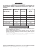
WATER CHEMISTRY (Corrosive water voids all warranties) For your health and the protection of your pool equipment, it is essential that your water be chemically balanced. The following levels must be used as a guide for balanced water. Fiberglass Pools Fiberglass Spas Other Pool & Spa Types Water Temp. (Deg. F) 68 to 88 89 to 104 68 to 104 pH 7.3 to 7.4 7.3 to 7.4 7.6 to 7.
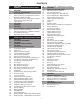
CONTENTS 4 PART ONE OWNER'S OPERATING INSTRUCTIONS 30 31 4 SECTION 1 START-UP PROCEDURES Before Start-Up Lighting Instructions & Shut-Off Procedures Manually Lighted Pilots MV Operating Instruction & Shut-Off Procedures Automatically Lighted Pilots IID After Start-Up SECTION 2 CAUTION SECTION 3 MAINTENANCE & CARE PROCEDURES Pool & Spa Water Chemistry Automatic Chlorinators & Chemical Feeders Cold Weather Operation Winterizing the Pool & Spa Heater PART TWO INSTALLATION & SERVICE INSTRUCTIONS SECTION 1 R
PART ONE OWNER'S OPERATING INSTRUCTIONS FOR YOUR SAFETY - READ BEFORE OPERATING WARNING: IF YOU DO NOT FOLLOW THESE INSTRUCTIONS EXACTLY, A FIRE OR EXPLOSION MAY RESULT, CAUSING PROPERTY DAMAGE, PERSONAL INJURY OR LOSS OF LIFE. SECTION 1 - START-UP PROCEDURES Your pool/spa heater has been designed for years of safe and reliable pool/spa water heating. It is available with millivolt or electronic ignition. ASME-certified units, typically used in commercial applications, are also available.
CAUTION: Propane gas is heavier than air and will settle on the ground. Since propane can accumulate in confined areas, extra care should be exercised when lighting propane heaters. LIGHTING INSTRUCTIONS AND SHUT-OFF PROCEDURES MILLIVOLT SYSTEM (MANUALLY LIGHTED PILOT) *If you cannot reach your gas supplier, call the fire department. A. This appliance has a pilot that must be lit by hand. When lighting the pilot, follow these instructions exactly. B.
CAUTION: Propane gas is heavier than air and will settle on the ground. Since propane can accumulate in confined areas, extra care should be exercised when lighting propane heaters. OPERATING INSTRUCTIONS AND SHUT-OFF PROCEDURES ELECTRONIC IGNITION SYSTEM (AUTOMATICALLY LIGHTED PILOT) A. *If you cannot reach your gas supplier, call the fire department. This appliance is equipped with an ignition device which automatically lights the pilot. Do not try to light the pilot by hand. B. C.
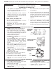
AFTER START-UP Feel the inlet and outlet pipes. Outlet pipe should be only slightly warmer than the inlet. It should not be hot. WARNING: Should overheating occur or the gas supply fail to shut off, turn off the manual gas control to the appliance. VISUAL INSPECTION - ATMOSPHERIC HEATERS With the heater on, remove the door and make a visual check of the pilot and burner. The flame should be blue with a well-defined pattern.
SECTION 3 - MAINTENANCE AND CARE PROCEDURES 2. Your pump strainer basket may be full. remove debris. WARNING: Check the heater for possible rodent nests after long periods of non-use. 3. Your filter may be dirty. If so, backwash or clean filter. (To tell if your filter is dirty, look to see if the filter pressure will be higher than usual). To be followed one month after start-up and then semiannually. If so 4. The pump may have lost its prime and be running dry. Check the pressure on the filter.
WINTERIZING THE POOL & SPA HEATER COLD WEATHER OPERATION IMPORTANT FREEZE INFORMATION Heaters installed outdoors in freezing climate areas may be shut down for the winter. Observe the following procedure for winterizing the heater: MODERATE CLIMATE: Heater operation can continue during short-term cold spells. When temperatures are between 0° and 32°F, flow (continuous pump operation) must be maintained. 1. Turn off gas valve, manual gas valve, and electrical supply to the heater. 2.
PART TWO INSTALLATION AND SERVICE INSTRUCTIONS SECTION 1 - RECEIVING EQUIPMENT The manufacturer recommends that this manual be reviewed thoroughly before installing your pool/spa heater. If there are any questions that this manual does not answer, please contact the factory or your local representative. On receipt of your equipment it is suggested that you visually check for external damage to the carton. If the carton is damaged, a note should be made on the Bill of Lading when signing for the equipment.
SECTION 2 - GENERAL SPECIFICATIONS These heaters are design-certified and tested under the latest requirements of the ANSI Z21.56 / CSA 4.7 Standard for Gas-Fired Pool Heaters. All heaters can be used either indoor or outdoors. The appropriate top designated for each type of use is required. If necessary, the top can be changed at a later date to change from outdoor to indoor or vice versa. Millivolt heaters contain a self-generating electrical system operating between .25 and .75 VAC.
CLEARANCES ALL HEATERS For clearances from combustible surfaces, see the chart below. When installed according to the listed minimum clearances from combustible construction, the pool heater can still be serviced without removing permanent construction around the heater. CLEARANCE FROM COMBUSTIBLE CONSTRUCTION However for ease of servicing, we recommend a clearance of at least 24” in the front, and at least 18" on the water connection side.
Heaters must not be installed under an overhang of less than three 3 ft from the top of the heater. Three sides must be open in the area under the overhang. Roof water drainage must be diverted away from the heaters installed under overhangs with the use of gutters. For U.S. installations, the point from where the flue products exit the heater must be a minimum of 4 ft below, 4 ft horizontally from, or 1 ft above any door, window or gravity inlet into any building.
FLORIDA BUILDING CODE 2001 WIND SPEED = 150 MPH, 3 SECOND GUST EXPOSURE = C 206/266/336/406 Atmospheric MODEL # B 206 20” 266 23” 336 26” 406 29” B 40” 28” 2” x 6” x 1/8” Pallet Anchor Bracket (4 Total) (Kit# 011636) 3” Min. Conc. Pad by others 1/4” x 1-3/4” S.S. Tapcon Bolt & Washer (Field Supplied) NOTE: Use hole closest to unit with washer overlapping edge of unit. Min. Edge Distance 6” Min. Edge Distance HOT 6” (1)–1/4” x 1-3/4” S.S. Tapcon Bolt & Washer (Field Supplied) Ea.
INDOOR HEATER INSTALLATION The heater is also design-certified for indoor installation when equipped with the approved drafthood. For Canada, indoor installation is restricted to an enclosure that is not occupied and does not directly communicate with an occupied area. Refer to the latest edition of CAN/CGA-B149 for specific requirements. Locate heater as close as is practical to a chimney or gas vent. Heater must always be vented to the outside. See Vent Piping section (pg. 17-18) for details.
SPECIFICATIONS AND DIMENSIONS ATMOSPHERIC UNITS Amp Draw 120 Volt 240 Volt B Digital 4 2 CL FLUE 10" D 8-7/8" 4-3/8" J* (6-5/8" ASME) (3-3/8" ASME) C INDOOR DRAFTHOOD 38" 32-11/16" 40" ELECTRICAL CONNECTION STACKLESS OUTDOOR TOP 26-5/8" (28-5/8" ASME) 13-1/4" GAS CONNECTION A 28" Shipping Weights (lbs) Standard ASME Heater Heater Indoor Water w/Stackless w/Stackless DraftConn. Top Top hood (A) Cabinet Width (B) Flue Dia.
SPECIFICATIONS AND DIMENSIONS Low NOx UNITS Amp Draw B 120 Volt 240 Volt 6 3 CL FLUE 10" 8-7/8” D C (6-5/8” ASME) 4-3/8” (3-3/8” ASME) J* INDOOR DRAFTHOOD 34” 26-1/2” STACKLESS OUTDOOR TOP ELECTRICAL CONNECTION 31-13/16" 20-1/2" (22-1/2" ASME) 7-3/4" GAS CONNECTION A 28” Shipping Weights (lbs) Standard ASME Heater Heater Indoor Water w/Stackless w/Stackless DraftConn. Top Top hood (A) Cabinet Width (B) Flue Dia. (C) Indoor Drafthood (D) Heater Model BTUH Input (000) R207A 199.
COMBUSTION AND VENTILATION AIR (Indoor Units Only) The heater must have both combustion and ventilation air. Minimum requirements for net free air supply openings are one opening that is 12 inches from the ceiling for ventilation, and one opening that is 12 inches from the floor for combustion air as outlined in the latest edition of the National Fuel Gas Code, ANSI Z223.1(CanadaCAN/CGA-B149) and any local codes that may have jurisdiction. B.
The discharge opening must be a minimum of 2 ft vertically from the roof surface and at least 2 ft higher than any part of the building within 10 ft. Vent stack shall be at least 5 ft in vertical height above the drafthood outlet. The vent cap location shall have a minimum clearance of 4 ft horizontally from, and in no case below, unless a 4 ft horizontal distance is maintained, from electric meters, gas meters, regulators and relief equipment.
GAS PRESSURE REGULATOR The gas pressure regulator is preset at 4.0 in. WC throughout for natural gas, and 10.5 in. WC. for propane gas. The pressure at the gas valve, taken with a manometer, should be about 4.0 in. WC natural gas (3.1 in. WC for Low NOx) and 10.5 in. WC propane gas. If an adjustment is needed, remove seal and turn adjustment screw clockwise to increase pressure or counter-clockwise to decrease pressure.
FLOW RATES MODEL PIPE SIZE 206/207 1-1/4”–1-1/2” - 2” MIN. GPM MAX. GPM* 20 125 266/267 336/337 1-1/4”–1-1/2” - 2” 1-1/4”–1-1/2” - 2” 25 35 125 125 406/407 1-1/4”–1-1/2” - 2” 40 125 *When flow rates exceed maximum GPM an external auxiliary bypass valve is required. See external bypass valve section for details.
POLYMER HEADERS (STANDARD MODELS) Before attaching the 2-inch unions to the inlet/outlet header, make sure the O-rings are properly seated in the grooves. Use AquaLube or equivalent non-petroleum-based lubricant on the O-ring. Hand tighten the unions. Glue PVC piping directly to the unions. required, use a silicon base such as AquaLube etc. There are two sets of flange gaskets supplied with your heater. Use the appropriate gaskets for all your heater connections. Discard unused set.
INTERNAL AUTOMATIC BYPASS VALVE PRESSURE RELIEF VALVE INSTALLATION In addition to the Unitherm Governor, a built-in automatic bypass valve is provided in the in/out header. While the Unitherm Governor responds to the changes in water temperature in the heater, the internal bypass valve automatically responds to changes in water pressure in the piping system. Proper amount of water flow is maintained through the heater under varying pressures dictated by the conditions of the pump and filter.
PLUMBING—WATER CONNECTIONS Single Pool Heater Installation Multiple Pool Heater Installation The heater requires water flow and positive pressure to fire and operate properly. It must therefore be installed downstream of the discharge side of the filter pump. A typical installation is plumbed as follows: 1. The inlet side of the filter is plumbed directly to the discharge side of the filter pump; 2. The outlet side of the filter is then plumbed to the inlet of the heater; and 3.
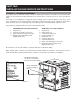
HEAT EXCHANGER REVERSAL PROCEDURE - STANDARD MODELS 1. Remove right and left side access panels (Figure 1). 2. Disconnect wires at high limit, AGS (automatic gas shut-off), and pressure switch on the in/out header (Figure 2). 3. Digital Models: Remove the thermostat temperature sensor by loosening the compression fitting nut (Figure 3). Re-route the sensor to the left side of the heater. 4. Millivolt Models: Remove the temperature sensor bulb and retainer clip from the sensor well (Figure 4).
ELECTRICAL WIRING OPTION LOCATION LEFT SIDE FIELD WIRING NOTE: If it is necessary to replace any of the original wiring, use 105°C wire or its equivalent, and/or 150°C wire or its equivalent, like the original wiring. CONTROL BOX (FACTORY MOUNTED LOCATION) MILLIVOLT MODELS The Millivolt models are equipped with a self-generating electrical system in which the electrical current is provided by a pilot generator. No external electrical connections are required.
TRANSFORMER WIRING 120 VAC WIRING For 120 VAC input power to the unit, connect the black wire to the “L1” or hot leg of the power supply. Connect the white wire to the “Ret” or neutral leg of the power supply. Attach the wire nut to the red wire. There should be no connection to the red wire for 120 VAC operation. For Low NOx pool heaters attach a wire nut to each red wire independently.
WIRING DIAGRAM - MILLIVOLT (MECHANICAL THERMOSTAT) 28
WIRING DIAGRAM - DIGITAL MODELS - ATMOSPHERIC 29
WIRING DIAGRAM - DIGITAL MODELS - LOW NOx 30
SECTION 4 - SERVICING INSTRUCTIONS GENERAL LOCATION OF CONTROLS ATMOSPHERIC Drain Plug (Located in rear header) Mounted On Top Of Header HL1 - High Limit HL2 - High Limit Pressure Switch Temp Sensor/Well Digital Thermostat Circuit Board Unitherm Governor Draw Plug Roll-Out Switch Transformer Gas Valve Pilot LOW NOx Drain Plug (Located in rear header) Draw Plug Digital Thermostat Circuit Board Blower Hose Mounted On Top Of Header HL1 - High Limit HL2 - High Limit Pressure Switch Temp Sensor/Well Unithe
CONTROL PANEL REMOVAL CONTROL ADJUSTMENTS - MILLIVOLT MODELS The water temperature is controlled by the heater thermostat on the upper front panel of the heater. The control center contains an On/Off switch and one thermostat. 1. Remove screw from front door. Set aside door for serviceability. KNURLED SCREW The thermostat is fitted with a means of limiting the upper temperature limit below the maximum level.
DIGITAL THERMOSTAT CONTROLS Thermostat operation Your heater is equipped with a microprocessor-controlled thermostat that controls the pool or spa temperature by measuring the temperature of the water coming back through the heater. It will then monitor the water temperature and turn the heater back on when it senses that the water temperature is falling below the set point. It is normal to experience small fluctuations in the return water temperature during the operation of the heater.
Program Button 1) To access the program screen, press the Mode button until the display reads OFF. Remove the four screws holding the control cover on. Swing control panel down so the back side of the board is visible (see page 30). Locate the Program Mode button as shown in the figure on pg. 32. Press the program button (5-7 seconds) until SETdef appears on the digital display. Release the program button. F/Cfff – Fahrenheit to Celsius Refer to step one above to access the program screen.
NOTE: The LCD temperature display may not agree with the temperature reading of your pool or spa thermometer. The heater reads the water temperature at the inlet. Due to the circulation characteristics of any pool or spa, the water temperature at the inlet to the heater may differ from that observed at a given location in the pool or spa. READING A FAULT DIAGNOSTICS The digital thermostat models are equipped with onboard diagnostic controls.
REMOTE CONTROL INSTALLATION AND OPERATION CAUTION: Before installing remote controls to the digital thermostat model heaters read the following: The digital thermostat model is remote-ready in most cases. The digital liquid crystal display (LCD) shows the actual pool temperature, operating status, and service codes (See examples below). The touch pad on the control panel allows you to select the desired pool or spa temperature.
REMOTE CONTROL WIRING Important Installation Notes for Remote or External Wiring Configuration • Remote wiring must be run in a separate conduit. • Remote wiring must not be run parallel to high voltage lines. • For runs of under 30 feet, remote wiring should have stranded conductors with a minimum of 22 AWG, 600V, cable twisting 1.5 to 2.5 in. lay and jacketed. • For runs over 30 feet, the conductors should be a minimum of 20 AWG, 600V, cable twisting 1.5 to 2.5 inch lay that is shielded and jacketed.
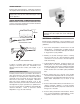
WATER PRESSURE SWITCH The water pressure switch, or heater actuator, ensures that the heater operates only when the filter pump is in operation. It is located on the inlet/outlet header. It is factory set at 1.75 PSI for deck-level installations. When the heater is located below the level of the spa or pool, it may be necessary to adjust the pressure switch to compensate for the no-flow static head.
BURNER TRAY REMOVAL ATMOSPHERIC MODELS 1. Shut off main electrical power switch to heater. 2. Shut off gas upstream of heater. 3. Remove front door. 4. Disconnect gas line from gas valve. 5. Remove (2) screws that mount burner tray to unit, and (2) screws that secure gas valve to jacket. 6. Disconnect wires that terminate at gas valve. 7. Disconnect hi-tension wire from PC board. 8. Slide out burner tray. 9. Reverse above procedure to reinstall. GAS VALVE REMOVAL ATMOSPHERIC MODELS 1.
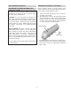
Extension Pieces (2) Auger with Carbide Tip TUBE CLEANING PROCEDURE Establish a regular inspection schedule, the frequency depending on the local water conditions and the severity of service. Do not let the tubes clog up solidly. Clean out deposits over 1/16" in thickness. Wire Brush IMMERSION WELL REPLACEMENT (Millivolt and ASME) 1. Shut off water to heater and drain heat exchanger. 2. Remove access panel on water connection side. 3. Remove old immersion well with bushing and sleeve. 4.
LOW NOx POOL HEATERS The Low NOx pool heaters are certified and tested under the ANSI Z21.56/CSA 4.7 Standard for GasFired Pool Heaters. BLOWER ADJUSTMENT This Low NOx pool heater is equipped with a combustion air plate (baffle) mounted on the air intake to the combustion air blower. The baffle has a hole that is utilized to control the air inlet to the blower. The heater should be installed to meet all local codes, and the latest editions of the National Fuel Gas Code Z223.
LOW NOx HEATERS (CONTINUED) MAIN BURNER AND ORIFICE REMOVAL BAFFLE MOUNTED INLET SIDE 1. Remove burner tray, following above procedure. 2. Remove pilot. See pilot removal procedure. 3. Remove (8) total screws from the burner holddown brackets, front and rear of tray. 4. Remove (8) total screws from the left and right sides of the manifold assembly. Detach the air/gas manifold assembly from the burner tray assembly. 5. Remove burners by raising them straight up off the rear end slots. 6.
SECTION 5 - TROUBLESHOOTING MECHANICAL IMPORTANT NOTICE These instructions are intended for the use of qualified personnel who are specifically trained and experienced in the installation of this type of heating equipment and related system components. Installation and service personnel may be required by some states to be licensed. Persons not qualified shall not attempt to install this equipment nor attempt repairs according to these instructions. PROBLEM CAUSE SOLUTION Harmonics, or whining noise U.G.
ELECTRICAL - STANDING PILOT MILLIVOLT POOL OR SPA HEATER ELECTRICAL CHECK WITH MILLIVOLT GAS VALVE CAUTION: For qualified service personnel only. 1. Filter must be on with adequate water flow through heater. 2. Gas valve must be in "ON" position. Thermostat set higher than pool water temperature. 3. Jumpers are for temporary check only. If left in place, they could cause the heater to burn up.
ELECTRICAL - ELECTRONIC IGNITION IID WARNING HIGH VOLTAGE For qualified technicians ONLY NOTE: Some heaters may be equipped with an ignition module that shuts off pilot gas if pilot fails to light. To reset, interrupt power to heater. START TURN GAS SUPPLY OFF. TURN THERMOSTAT (CONTROLLER) TO CALL FOR HEAT POWER TO PC BOARD? (24 V NOMINAL) YES SPARK ACROSS IGNITER/SENSOR GAP? YES NOTE: Before troubleshooting, familiarize yourself with the start-up and check-out procedure.
DIGITAL CONTROL LOGIC - FLOW CHART Power On Is the water temperature displayed? NO • Check On/Off switch (under lid on control panel) • Check for 120/240 volts to the transformer (time clock, circuit breaker, wire connections) • Check for 24 volts to Circuit Board (P6 connector) YES REM and Water Temperature displayed and flashing (a remote control is controlling the heater) Note: Disconnect the remote by turning the remote function off. See page 35 for instructions.
SECTION 6 - REPLACEMENT PARTS NOTE: To supply you with the correct part, it is important that you supply the heater model number, serial number and type of gas when applicable. If determined defective by the Company and within warranty, a like part or equal substitution will be returned, freight collect. Credit will not be issued.
3-V ATMOSPHERIC HEATERS 1-S 14-M 13-S 4-V 1-V 2-S 6-HP 2-V 5-HP 7-HP 12-HM 3-HP 3-R 14-M 6-HP 4-HP 12-S 6-S 4-S 7-S 17-HM 11-S 8-S 10-M 5-C 9-M 9-M 4-C 2-R 4-S 2-M 4-M 11-M 2-B 2-J 13-M 5-M 12-M 3-S 1-G 16-M 16-M 5-S 3-B 5-B 10-S 1-B 48 4-B 1-J 1-R
LOW NOx HEATERS 49
3-M (OPTIONAL) 6-C 14-HM 2-S 16-HM 13-HM 9-S 1-M 15-HM 2-C 6-HM 5-HM 2-HM 3-C 12-HM 7-HM 4-HM 10-HM 4-S 3-HM 8-HM 17-HM 11-HM 9-HM 2-P 7-P 9-P HONEYWELL IID ATMOSPHERIC PILOT POLYMER IN/OUT HEADER AND ACCESSORIES 1-P 1-P 5-P 8-P 2-P 6-P 6-P 3-P 4-P 9-P HONEYWELL MILLIVOLT PILOT IID LOW NOx PILOT 50
ATMOSPHERIC HEATERS CALL OUT B 1-B DESCRIPTION BURNER TRAY Burner Tray w/Burners (sea level)* Burner Tray w/o Burners (sea level)* Burner Tray w/Gas Valve Nat Millivolt Burner Tray w/Gas Valve Pro Millivolt Burner Tray w/Gas Valve Nat IID Burner Tray w/Gas Valve Pro IID 2-B Burner Spacer/Hold Down Kit 3-B Burner 4-B Burner Orifice Nat. #50 (Sea Level)* Burner Orifice Pro.
ATMOSPHERIC HEATERS CALL OUT HM 1-HM 2-HM 15-HM 16-HM 3-HM 4-HM 5-HM 6-HM 7-HM 8-HM 9-HM 10-HM 11-HM 12-HM 13-HM 14-HM 17-HM J 1-J 2-J M 1-M 2-M 3-M 4-M 5-M 6-M 7-M 8-M 9-M 10-M 11-M 12-M 13-M 14-M 15-M 16-M 17-M P 1-P 2-P 3-P Pilot Nat & Pro IID 4-P 5-P 6-P 7-P 8-P 9-P 10-P 11-P R 1-R 2-R 3-R DESCRIPTION HEAT EXCHANGER - METAL Heat Exchange Assy.Copper ASME CI Heat Exchange Assy.
ATMOSPHERIC HEATERS CALL OUT S 1-S 2-S 3-S 4-S 5-S 6-S 7-S 8-S 9-S 10-S 11-S 12-S 13-S V 1-V 2-V 4-V 3-V DESCRIPTION SHEETMETAL Jacket Top (Louvered) Flue Collector (Units with Polymer Header) Flue Collector (Units with Metal Header) Door Assy. Raypak Rheem Access Panel Set (3 Pcs Units with Polymer Header) Access Panel Set (3 Pcs.
LOW NOx HEATERS CALL OUT BB 1-B DESCRIPTION 207A 267A 337A 407A BURNER TRAY*** Burner Tray w/Burners (0-5000) 010343F 010344F 010345F 010346F 010087F Burner Tray w/o Burner (0-5000) 010084F 010085F 010086F 2-B Burner Hold Down Kit 010254F 010255F 010256F 010257F 3-B Burner 310732/3 310732/4 310732/5 310732/6 351510/3 351510/4 351510/5 351510/6 4-B Burner Orifice Nat. #26 (0-5000)* Burner Orifice Nat. #31 (above 5000 ft.
LOW NOx HEATERS CALL OUT J 1-J 2-J 3-J M 1-M 2-M 3-M 4-M 5-M 6-M 7-M 8-M 9-M 10-M 11-M 12-M 13-M 14-M P 1-P 2-P 3-P 4-P 5-P 6-P R 1-R 2-R 3-R S 1-S 2-S 3-S 4-S 5-S 6-S 7-S 8-S 9-S 10-S 11-S 12-S 13-S V 1-V 2-V 4-V 3-V DESCRIPTION CONTROL BOX Transformer 120/240/24V Rocker Switch Relay Low Nox MISCELLANEOUS COMPONENTS Pressure Switch 1.75 PSI Pressure Switch 11 PSI Special-See Water Pressure Switch Adj.