INSTALLATION AND OPERATION MANUAL Gas-Fired Pool and Spa Heater Bronze ASME and Polymer Atmospheric Heat Exchanger Models 206A, 266, 266A, 336A, 399, and 406A A S M E HLW BR models only A WARNING: If the information in the instructions is not followed exactly, a fire or explosion may result causing property damage, personal injury or death. - Do not store or use gasoline or other flammable vapors and liquids or other combustible materials in the vicinity of this or any other appliance.
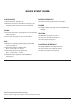
QUICK START GUIDE CLEARANCES WATER CHEMISTRY Space required: See page 12. Water chemistry requirements: See page 5. Minimum and service clearances: See page 7 for clearances table. Note that local codes prevail. POWER PIPING Pressure relief valve: See page 20 for recommended PRV orientation. Flow rates: See page 17 for flow rate values. GAS Supply voltage: See page 23 for acceptable input voltages. VENTING Materials: See pages 11 and 14. D-2 Power Vent Kit: See page 14.
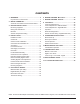
CONTENTS 1. WARNINGS.............................................................. 4 Pay Attention to These Terms.................................. 4 6. WIRING DIAGRAM - MILLIVOLT........................ 24 2. WATER CHEMISTRY.............................................. 5 Automatic Chlorinators and Chemical Feeders....... 5 8. CONTROLS............................................................ 26 Control Panel Removal.......................................... 26 Control Adjustments - Millivolt Models..
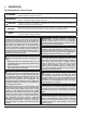
1. WARNINGS Pay Attention to These Terms A DANGER Indicates the presence of immediate hazards which will cause severe personal injury, death or substantial property damage if ignored. A WARNING Indicates the presence of hazards or unsafe practices which could cause severe personal injury, death or substantial property damage if ignored. A CAUTION Indicates the presence of hazards or unsafe practices which could cause minor personal injury or product or property damage if ignored.
A CAUTION: Elevated water temperature can be hazardous. The U.S. Consumer Product Safety Commission has these guidelines: 1. Spa water temperatures should never exceed 104°F (40°C). A temperature of 100°F (38°C) is considered safe for a healthy adult. Special caution is suggested for young children. 2. WATER CHEMISTRY NOTE: Damage due to poor water chemistry is not a warrantable defect. Chemical imbalance can cause severe damage to your heater and associated equipment.
skimmer. High chemical concentrations will result when the pump is not running (e.g. overnight). THE MODEL AND SERIAL NO. CAN ALSO BE FOUND INSIDE THE BEZEL ABOVE THE DISPLAY Chlorinators must feed downstream of the heater and have an anti-siphoning device to prevent chemical backup into the heater when the pump is shut off. See "Plumbing Diagrams" on page 21. NOTE: High chemical concentrates from feeders and chlorinators that are out of adjustment will cause rapid corrosion to the heat exchanger.
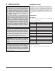
4. INSTALLATION A WARNING: This unit contains refractory ceramic fiber (RCF) insulation in the combustion chamber. RCF, as manufactured, does not contain respirable crystalline silica. However, following sustained exposure to very high temperatures (>2192°F), the RCF can transform into crystalline silica (cristabolite). The International Agency for Research on Cancer (IARC) has classified the inhalation of crystalline silica (cristabolite) as carcinogenic to humans.
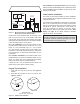
When installed according to the listed minimum clearances from combustible construction, the pool heater can still be serviced without removing permanent construction around the heater. However for ease of servicing, we recommend a clearance of at least 24" (610 mm) in the front, and at least 18" (457 mm) on the water connection side. This will enable the heater to be serviced in its installed location, that is, without movement or removal of the heater. Description a. b. c. d. e. f. g. h.
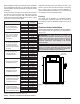
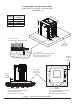
For installations in Florida and Texas, that must comply with the Florida or Texas Building Code, follow the directions shown in Figure 5 for the installation of hurricane tie-down brackets for all models. 4' (1.2 m) Minimum 4' (1.2 m) Minimum 4' (1.2 m) Minimum 3' (0.9 m) Minimum 10' (3 m) Minimum 1' (0.3 m) Minimum Forced Air Inlet Figure 3. Minimum Distances to Building Openings from Where Flue Products Exit the Boiler Heaters must not be installed under an overhang of less than 3' (0.
FLORIDA AND TEXAS BUILDING CODES WIND SPEED = 150 MPH, 3 SECOND GUST EXPOSURE = C Model B in. (mm) 206A 20 (508) 266/266A 23 (584) 336A 26 (660) 399/406A 29 (737) B 38" (965 mm) F10648 28" (711 mm) 2" x 6" x 1/8" Pallet Anchor Bracket (4 Total) (Kit# 011636) 3" (76 mm) Min. Conc. Pad by others 1/4" x 1-3/4" S.S. Tapcon Bolt and Washer (Field-Supplied) NOTE: Use hole closest to unit with washer overlapping edge of unit. Min. Edge Distance 6" (152 mm) 3" (76 mm) Min. Conc.
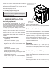
Combustion and Ventilation Air Outdoor and Indoor Stacks The outdoor and indoor stacks are optional equipment and do not come standard with the heater. Refer to installation instructions inside box for instructions on how to install outdoor/indoor stack. Model Outdoor Stack Indoor Stack 206A 009834 009838 266/266A 009835 009839 336A 009836 009840 399/406A 009837 009841 Table D.
Specifications and Dimensions Amp Draw 120 VAC, 1Ph, 60Hz 240 VAC, 1Ph, 60Hz 4 2 B CL Flue C Indoor Drafthood D J* WATER INLET 2" SLIP 4-3/8" (111 mm) (3-3/8" ASME) (86 mm ASME) 10" (254 mm) 8-7/8" (225 mm) 6-5/8" ASME (168 mm ASME) 38” (965 mm) GAS, 3/4" NPT 40" (1016 mm) Stackless Outdoor Top 32-11/16" (830 mm) Electrical Connection 26-5/8” (676 mm) 28-5/8” ASME (727 mm ASME) WATER OUTLET 2" SLIP 13-1/4” (337 mm) gas connection Figure 8. 28" (711 mm) F10646 A Front View Figure 9.
Shipping Weights lbs (kg) Residential - Cupronickel Heat Exchanger Heater Mode BTUH Input (000) (kw) (A) (B) (C) Cabinet Flue Indoor Width Dia. Drafthood in. (mm) in. (mm) in. (mm) (D) in. (mm) (J)* in. (mm) Standard Heater w/Stackless Top Indoor Drafthood P-_206A-EN-X 180.0 (52.7) 20 (508) 6 (152) 61-5/8 (1565) 10.0 (254) 11-3/4 (298) 187 (85) 14 (6.4) P-_266A-EN-X 240.0 (70.3) 23 (584) 7 (178) 62 (1575) 11.5 (292) 11 (279) 210 (95) 16 (7.3) P-_336A-EN-X 300.0 (87.
Vent Piping A WARNING: Indoor heaters require a drafthood that must be connected to a vent pipe and properly vented to the outside. Failure to follow this procedure can cause fire or fatal carbon monoxide poisoning. When properly installed outdoors, only the outdoor stackless top (provided) is required.
2' MIN (0.6 m) 8' (2.4 m) OR LESS VENT CAP 2' MIN (0.6 m) 5' MIN (1.5 m) VENT PIPE Gas piping must have a sediment trap ahead of the heater gas controls, and a manual shutoff valve located outside the heater jacket. All gas piping should be tested after installation in accordance with local codes. A CAUTION: The heater and its manual shutoff valve must be disconnected from the gas supply during any pressure testing of that system at test pressures in excess of 1/2 psi (3.45 kPa).
Gas Pressure Adjustment Locations Millivolt Gas Valve GAS PRESSURE ADJUSTMENT Figure 14. Robertshaw 7000 (Heater Models 206A - 406A) Electronic Ignition Gas Valves GAS PRESSURE ADJUSTMENT Figure 15. Honeywell VR8340 (Heater Models 206A - 406A) GAS PRESSURE ADJUSTMENT Figure 16. Robertshaw 7200 (Heater Model 206A) 16 GAS PRESSURE ADJUSTMENT Figure 17. Robertshaw 7000 BDER (Heater Models 266A 336A) GAS PRESSURE ADJUSTMENT Figure 18.
Pipe Sizing for Gas Connection These capacities shown below based on using SCH 40 black iron pipe. For capacities using other materials, consult local code. Maximum Equivalent Pipe Length (ft) (m) Natural Gas 1000 BTU/FT3 0.60 Specific Gravity @ 0.5 in WC Pressure Drop Propane Gas 2500 BTU/FT3 1.53 Specific Gravity @ 0.5 in WC Pressure Drop Model 206A 266/266A 336A 399/406A 3/4" 1" 1-1/4" NAT PRO NAT PRO NAT PRO 1-1/2" NAT PRO 25 60 90 215 360 (7.6) (18.3) (27.4) (65.5) (109.7) F10637-1 Figure 20.
Flow GPM (lpm) Pressure Drop (Ft. of Head) (m of Head) 206A 266A 336A 8.2 30 (113) 9.5 9.5 40 (151) 9.7 9.7 11 13.4 50 (189) 10 9.8 12.2 13.4 60 (227) 11 10.4 13.7 13.5 70 (265) 11.5 10.9 14.3 14 80 (303) 12.6 12 15.5 15 90 (340) 14 13 16.2 16.2 100 (378) 15 14.2 17.5 16.7 HEADER FLANGE NUT (CPVC) Bronze Heat Exchanger Pressure Drop - ASME Models (UG Closed) NOTE: Table capacity is based on schedule 40 black iron pipe.
Follow the steps below to replace the ProTek Shield Assy: 1. Shut off the pool pump and bleed pressure from the system. 2. Close isolation valves to minimize pool/spa water loss. 3. Remove wing nut from bottom stud on ProTek Shield Assy. 4. Remove bonding wire ring terminal from stud. 5. Rotate ProTek Shield Assy clockwise (by hand) to unscrew it from the assembly. Internal Automatic Bypass Valve In addition to the Unitherm Governor, a built-in automatic bypass valve is provided in the In/Out header.
Auxiliary Bypass Valve Adjustment To set bypass, with clean filter, adjustment is made by feeling the inlet and outlet pipes at the heater. Outlet pipes should be slightly warmer than inlet and comfortable to the touch. If pipe is hot, close bypass; if cold, open bypass. Pressure Relief Valve Installation NOTE: To avoid water damage or scalding due to valve operation, drain pipe must be connected to valve outlet and run to a safe place of discharge.
Plumbing Diagrams Water Connection ISOLATION VALVE BALL VALVE THIS DIAGRAM IS A RECOMMENDATION AND IS NOT INTENDED TO REPACE AN ENGINEERED PIPING SYSTEM BY A PROFESSIONAL ENGINEER Figure 31. Single Heater Installation PRESSURE RELIEF VALVE PUMP UNION CHECK VALVE THIS DIAGRAM IS A RECOMMENDATION AND IS NOT INTENDED TO REPACE AN ENGINEERED PIPING SYSTEM BY A PROFESSIONAL ENGINEER Figure 32.
2. Disconnect wires at high limit, AGS (automatic gas shutoff), water pressure switch on the in/out header and ProTek Shield bonding wire. See Figure 33. 5. Reconnect high limit, AGS, water pressure switch wires, and ProTek Shield bonding wire. 6. Digital Models: Insert the temperature sensor into the compression fitting, so that the sensor is flush with the top of the fitting. Tighten 1/2 turn past hand-tight. Millivolt Models: Insert sensor bulb and retainer clip into sensor well. 7.
8. Re-route all high-voltage wires and ground wires through the left jacket side of heater. There should be no connection to the red wire for 120 VAC operation. Attach a wire nut to the red wire. 9. Re-install P6 connector, ground wires (SPG), transformer, junction box, front door, and plug right side with the left side’s grommet plug. NOTE: 7/8" diameter holes not utilized on jacket and control box can be used for fireman switch, auxiliary control interface or power vent (D-2) wiring.
6.
7.
8. CONTROLS NOTE: Caution must be used to not damage controls or wiring. PRESSURE SWITCH TEMP SENSOR HL1 - HIGH LIMIT HL2 - HIGH LIMIT CONTROL BEZEL KNURLED SCREW UNITHERM GOVERNOR F10646-5 Figure 41. Knurled Screw Location ROLL-OUT SWITCH GAS VALVE F10640-2 Control Adjustments Millivolt Models PROTEK SHIELD ASSY The water temperature is controlled by the heater thermostat on the upper front panel of the heater. The control center contains an On/Off switch and one thermostat. Figure 39.
Control Adjustments – Digital Models The pool heater touchpad, located on the upper front panel of the heater, allows the user to select either POOL or SPA operation, and to adjust the setpoint temperature. The LCD display window indicates the mode (OFF, SPA, POOL) and the actual water temperature. A manual power switch provided below the touchpad turns the control power ON or OFF. See Figure 43. TEMP ADJUST BUTTONS MODE BUTTON Program Mode Button (SW1) Figure 45.
Press the DOWN button. The Fault History displays up to ten faults in memory. The order of the faults begins with “Fault Last,” which is the most recent fault, and proceeds through ten most recent messages in chronological order. The second line of the display shows the fault message. If there are no faults in the history buffer, the second line reads “All Faults Clear.” Both the POOL and SPA setpoints will revert to 65°F (18°C) and both POOL and SPA maximum temperature settings will be 104°F (40°C).
NOTE: Both the POOL and SPA setpoints will revert back to 65°F (18°C) and the POOL and SPA maximum temperature settings will be 104°F (40°C). These setpoints will need to be readjusted to desired settings. NOTE: The LCD temperature display may not agree with the temperature reading of your pool or spa thermometer. The heater reads the water temperature at the inlet.
Remote Control Installation and Operation A CAUTION: Before installing remote controls to the digital heaters, read the following: The digital thermostat model is remote-ready in most cases. The digital liquid crystal display (LCD) shows the actual pool temperature, operating status, and service codes. See Figure 51. The touch pad on the control panel allows you to select the desired pool or spa temperature.
• For both two- and three-wire remote systems, the provided 7-pin wiring connector must be utilized. 3. Turn the MODE button to “OFF” and remove power from the heater. NOTE: The remote wires must be connected to the 7-pin connector before the connector is plugged into the board. 2-Wire Remote Control (On-Off) This application assumes that only one heating function (pool or spa) is required. 1. Turn on power to the heater. 2.
For millivolt heaters, the fireman's switch connection is a wire nut located in the Violet/Black wiring between the manual toggle switch and the gas valve. heaters, splice into the red/white wire to connect the time clock. For digital heaters, the fireman’s switch connection is located on the 14-pin header connected to the digital control board. Splice into the red wire jumper tagged – Where necessary add “Fireman’s” switch circuit here – to connect the time clock. 8.
A CAUTION: Do not operate the heater without the function of a properly-adjusted water pressure switch or flow switch. Flame Roll-Out Safety Switch Heaters are equipped with a thermal cutoff device to prevent flame roll-out in the event the heat exchanger becomes blocked. This is a “single-use” type fusible link or thermal fuse, that must be replaced when disabled by an over-temperature condition, caused by excessive restriction in the heat exchanger flue passage.
4. Turn vertical gas pipe from manifold slightly and unscrew gas valve. 5. Reverse above procedure to reinstall. Main Burner And Orifice Removal 1. Remove burner tray, following above procedure. 2. Remove screws and burner hold-down bracket. NOTE: If the heat exchanger is sooted badly, the burner hold-down bracket and spacer can become distorted from direct-flame impingement and this usually necessitates replacement of these parts. 3. Lift burners from slotted spacers and slide from orifices.
1. Remove top and flue collector from cabinet. 2. Remove “V” baffles from heat exchanger. 3. Remove burner tray. See page 33. 4. If ProTek Shield Assy is attached to the heater, remove ProTek Shield Assy bonding wire from heat exchanger stud. 5. Remove heat exchanger from the heater and wash with a garden hose, making sure soot is removed from spaces between fins. 6. Reverse above procedure to reinstall. NOTE: In extreme cases it may be necessary to do steam cleaning at the local car wash.
9. OPERATING INSTRUCTIONS Visual inspection With the heater on, remove the door and make a visual check of the pilot and burner. The flame should be blue with a well-defined pattern. Before Start-Up Burners Keep heater area clear and free from combustibles, flammable liquids and chemicals. Do not obstruct the flow of combustion and ventilation air. A yellow or “floating” flame indicates restricted air openings or incorrect orifice size.
OPERATING INSTRUCTIONS AND SHUTOFF PROCEDURES MILLIVOLT SYSTEM (MANUALLY-LIGHTED PILOT) FOR YOUR SAFETY READ BEFORE LIGHTING A. This appliance has a pilot which must be lit by hand. When lighting the pilot, follow these instructions exactly. B. BEFORE LIGHTING, smell all around the appliance area for gas. Be sure to smell near the floor because some gas is heavier than air and will settle on the floor. WHAT TO DO IF YOU SMELL GAS: *Do not try to light any appliance.
OPERATING INSTRUCTIONS AND SHUTOFF PROCEDURES ELECTRONIC IGNITION DIGITAL MODELS (AUTOMATICALLY-LIGHTED PILOT) FOR YOUR SAFETY READ BEFORE LIGHTING A. This appliance is equipped with an ignition device which automatically lights the pilot. Do not try to light the pilot by hand. B. BEFORE OPERATING, smell all around the appliance area for gas. Be sure to smell near the floor because some gas is heavier than air and will settle on the floor. WHAT TO DO IF YOU SMELL GAS: *Do not try to light any appliance.
10. MAINTENANCE AND CARE A WARNING: Check the heater for possible rodent nests after long periods of non-use. To be followed one month after start-up and then semiannually. 1. Inspect the top of the heater and drafthood for soot, a sticky black substance around finned tubes and “V” baffles, and open flue gas passageways. Any visible soot should be cleaned for proper operation. A CAUTION: Soot may be combustible. Wet sooted surfaces completely prior to cleaning. Do not use steel wire brush. 2.
11. TROUBLESHOOTING IMPORTANT NOTICE: These instructions are intended for the use of qualified personnel who are specifically trained and experienced in the installation of this type of heating equipment and related system components. Installation and service personnel may be required by some states to be licensed. Persons not qualified shall not attempt to install this equipment nor attempt repairs according to these instructions. Problem Harmonics, or whining noise Possible Cause Corrective Action U.G.
Millivolt - Flow Chart Light pilot If pilot burner goes out when main burner lights or when gas valve knob is released If pilot burner remains lit Jump across both "TH" wires on gas valves If main burner fires, remove jumper If main burner does not fire, remove jumper Jump across pressure switch terminals If pilot burner stays on If main burner fires, remove jumper If main burner does not fire, remove jumper Clean filter Jump across thermostat Check for adequate water flow from filter If main bur
Digital - Flow Chart A WARNING: HIGH VOLTAGE For qualified technicians ONLY NOTE: Some heaters may be equipped with an ignition module that shuts off pilot gas if pilot fails to light. To reset, interrupt power to heater. START TURN GAS SUPPLY OFF. TURN THERMOSTAT (CONTROLLER) TO CALL FOR HEAT POWER TO PC BOARD? (24 V NOMINAL) YES SPARK ACROSS IGNITER/SENSOR GAP? YES NOTE: Before troubleshooting, familiarize yourself with the start-up and check-out procedure.
Control Logic - Flow Chart - Digital Power On Is the water temperature displayed? NO YES “Remote” and Water Temperature displayed (a remote control is controlling the heater) Push MODE switch to select "Pool" or "Spa" Note: Disconnect the remote by turning the remote function off. See page 30 for instructions.
12. REPLACEMENT PARTS NOTE: To supply you with the correct part, it is important that you supply the heater model number, serial number and type of gas when applicable. Any part returned for replacement under standard company warranties must be properly tagged with a return parts tag, completely filled in with the heater serial number, model number, etc., and shipped to the Company freight prepaid.
13.
2-S 6-C 8-HP 27-HM 5-HM 26-HM 2-HM 1-M 7-HM 3-HM 1-C 9-C 8-HP 21-M 6-HM 1-M 6-C INLET 4-HM OUTLET 4-S 18-HP 28-HM 17-HP 6-M 20-HP FOR UNITS WITH ASME BRONZE HEADERS FROM 12/2019 (PROTEK SHIELD AVAILABLE ON ASME HEATERS AFTER END OF Q3 2020) 2-S 13-HM 1-M 5-HM 6-HM 6-M (OPTIONAL) 6-C 14-HM 16-HM 9-S 2-C 2-HM 3-C 7-HM 15-HM 12-HM 4-HM 4-S 3-HM 17-HM 10-HM 18-HM 8-HM 9-HM UNITS WITH ASME CAST IRON HEADERS, DISCONTINUED 12/2019 30-HM INLET PROTEK SHIELD ADAPTER KIT 46 11-H
19-HP 6-M (OPTIONAL) 19-HP 1-M 1-M 6-M (OPTIONAL) 6-C 11-HP 19-HP 11-HP 1-C 6-C 8-HP 10-HP 12-HP 26-HM 16-HP OUTLET 22-M 27-HM 18-HP 2-HP 13-HP 24-M 23-M OUTLET 18-HP 23-M 17-HP 13-HP 17-HP 10-HP 24-M 2-HP INLET 14-HP 16-HP 12-HP 8-HP 18-HP 15-HP 14-HP 17-HP INLET 20-HP 29-HM FOR UNIT S WITH PO LYMER HEADERS FR OM 1 0 / 2 0 1 9 PROTEK ADPTER AND POLYMER UNITS PRIOR TO 10/2019 1-P 2-P 5-P 8-P 7-P 6-P 9-P 3-P 9-P HONEYWELL IID ATMOSPHERIC PILOT HONEYWELL MILLIVOLT PI
CALL OUT B 1-B 2-B 3-B 4-B 5-B C 1-C 2-C 3-C 4-C 7-C 8-C 5-C 6-C 9-C G 1-G 1-HP HP 2-HP 3-HP 4-HP 5-HP 6-HP 7-HP 8-HP 9-HP 10-HP 11-HP 12-HP 13-HP 14-HP 15-HP 16-HP 17-HP 18-HP 19-HP 20-HP DESCRIPTION BURNER TRAY Burner Tray w/Burners (sea level)* Burner Tray w/o Burners (sea level)* Burner Tray w/Gas Valve Nat Millivolt Burner Tray w/Gas Valve Pro Millivolt Burner Tray w/Gas Valve Nat IID Burner Tray w/Gas Valve Pro IID Burner Spacer/Hold Down Kit Burner Burner Orifice Natural Gas Burner Orifi
CALL OUT HM 1-HM DESCRIPTION 206A 266/266A 399/406A HEAT EXCHANGER - METAL Heat Exchanger Assy.Copper ASME Units manufactured from 12/2019 (Bronze) 017983F 017984F 017986F Units manufactured prior to 12/2019 (Cast Iron) 010051F 016193F 010054F Heat Exchanger Assy.
CALL OUT P 1-P 2-P 3-P PILOT Pilot Nat. MV Pilot Pro. MV DESCRIPTION Pilot Nat & Pro IID Pilot Orifice Nat. MV Pilot Orifice Pro. MV 4-P Pilot Orifice Nat. IID .020 Pilot Orifice Pro. IID .
NOTES 51