
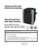
Instructions / Assembly

7
4. INSTALLATION
A
WARNING: This unit contains refractory ceramic
ber (RCF) insulation in the combustion chamber. RCF,
as manufactured, does not contain respirable crystalline
silica. However, following sustained exposure to very
high temperatures (>2192°F), the RCF can transform
into crystalline silica (cristabolite). The International
Agency for Research on Cancer (IARC) has classied
the inhalation of crystalline silica (cristabolite) as
carcinogenic to humans.
When removing the burners or heat exchangers, take
precautions to avoid creating airborne dust and avoid
inhaling airborne bers. When cleaning spills, use wet
sweeping or High Eciency Particulate Air (HEPA)
ltered vacuum to minimize airborne dust. Use feasible
engineering controls such as local exhaust ventilation
or dust collecting systems to minimize airborne dust.
Wear appropriate personal protective equipment
including gloves, safety glasses with side shields, and
appropriate NIOSH-certied respiratory protection,
to avoid inhalation of airborne dust and airborne ber
particles.
IMPORTANT NOTICE: These instructions are intended
only for the use by qualied personnel, specically
trained and experienced in the installation of this type
of heating equipment and related system components.
Installation and service personnel may be required by
some states to be licensed. If your state is such, be sure
your contractor bears the appropriate license. Persons
not qualied shall not attempt to x the equipment nor
attempt repairs according to these instructions.
A
WARNING: Improper installation, adjustment,
alteration, service or maintenance may damage the
equipment, creating a hazard resulting in asphyxiation,
explosion or re. Such damage is not covered under
warranty.
NOTE: The heater should not be located in an area
where possible water leakage will result in damage to
the area adjacent to the heater or to the structure. When
such locations cannot be avoided, it is recommended
that a suitable drain pan, with adequate drainage, be
installed under the heater. The pan must not restrict
combustion air ow.
Installation Codes
Installation must be in accordance with local codes, or,
in the absence of local codes, with the latest edition of
the National Fuel Gas Code, ANSI Z223.1/NFPA54 and
National Electrical Code, ANSI/NFPA 70, and for Canada,
the latest edition of CAN/CSA-B149 Installation Codes,
and Canadian Electrical Code, CSA C22.1 Part 1 and
Part 2.
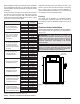
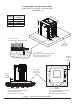
Clearances
All Heaters
For indoor and outdoor clearances from combustible
surfaces, see the chart below.
Location Indoor Installation
Top * 30" (762 mm) Drafthood
Front Alcove (Open)
Vent 6" (152 mm)
Floor ** 0"
Back 6" (152 mm)
Right Side 12" (305 mm) Water Side
Left Side 6" (152 mm) Opposite Water Side
Location Outdoor Installation
Top * Unobstructed (Outdoor Stack)
Top *** 36" (914 mm) (Stackless Top)
Floor 0"
Back 6" (152 mm)
Right Side 12" (305 mm) Water Side
Left Side 6" (152 mm) Opposite Water Side
* Clearance from top of vent terminal
** Do not install on carpeting
*** Clearance from top of heater
Table B. Minimum Clearances from Combustible Surfaces