
Instructions / Assembly

8
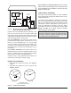
When installed according to the listed minimum clearances
from combustible construction, the pool heater can still be
serviced without removing permanent construction around
the heater.
However for ease of servicing, we recommend a clearance
of at least 24" (610 mm) in the front, and at least 18" (457
mm) on the water connection side. This will enable the
heater to be serviced in its installed location, that is, without
movement or removal of the heater.
Description Location
Distance
in. (mm)
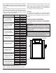
a. 3-1/2" (89 mm) thick
masonry walls without
ventilated air space
Back 9 (229)
Right 9 (229)
Left 9 (229)
Vent 5 (127)
Indoor Top 39 (991)
Outdoor Top Unobstructed
b. 1/2" (13 mm)insulation
board over 1" (25 mm)
glass ber or mineral
wool batts
Back 6 (152)
Right 6 (152)
Left 6 (152)
Vent 3 (76)
Indoor Top 30 (762)
Outdoor Top Unobstructed
c. 0.024 sheet metal over
1" (25 mm) glass ber
or mineral wool batts
reinforced with wire on
rear face with ventilated
air space
Back 4 (102)
Right 4 (102)
Left 4 (102)
Vent 3 (76)
Indoor Top 24 (610)
Outdoor Top Unobstructed
d. 3-1/2" (89 mm) thick
masonry wall with
ventilated air space
Back 6 (152)
Right 6 (152)
Left 6 (152)
Vent 6 (152)
Indoor Top 39 (991)
Outdoor Top Unobstructed
e. 0.024 sheet metal with
ventilated air space
Back 4 (102)
Right 4 (102)
Left 4 (102)
Vent 2 (51)
Indoor Top 24 (610)
Outdoor Top Unobstructed
f. 1/2" (13 mm) thick
insulation board with
ventilated air space
Back 4 (102)
Right 4 (102)
Left 4 (102)
Vent 3 (76)
Indoor Top 24 (610)
Outdoor Top Unobstructed
g. 0.024 sheet metal with
ventilated air space over
0.024 sheet metal with
ventilated air space.
Back 4 (102)
Right 4 (102)
Left 4 (102)
Vent 3 (76)
Indoor Top 24 (610)
Outdoor Top Unobstructed
h. 1" (25 mm) glass ber
or mineral wool batts
sandwiched between two
sheets 0.024 sheet metal
with ventilated air space
Back 4 (102)
Right 4 (102)
Left 4 (102)
Vent 3 (76)
Indoor Top 24 (610)
Outdoor Top Unobstructed
Derived from National Fuel Gas Code, Table 10.2.3
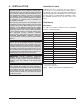
Table C. Reduction of Clearances to Protected Surfaces
Clearances less than these may require removal of the
heater to service either the heat exchanger or the burner
tray. In either case, the heater must be installed in a
manner that will enable the heater to be serviced without
removing any structure around the heater.
Flooring
This heater can be installed on combustible ooring.
The combustible clearances listed can be reduced by
protecting the exposed combustible surfaces as shown in
Table C.
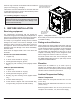
Outdoor Heater Installation
These heaters are design-certied for outdoor installation,
when equipped with the approved tops designated for
outdoor use.
A
WARNING: The heater shall not be located in an
area where water sprinklers, or other devices, may cause
water to spray through the cabinet louvers and into the
heater. This could cause internal rusting or damage
electrical components. Such damage is not covered
under warranty.
A
WARNING: Do not install within 3' (0.9 m) of a heat
pump or an outdoor condensing unit. Strong air intake
from this type of equipment can disturb the combustion
process and cause damage or personal injury.
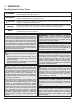
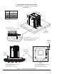
F10646-1
PAGODA TOP
INSTALLATION
Figure 2. Heater with Outdoor Stackless Top