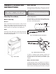
INSTALLATION & OPERATING INSTRUCTIONS Versa™ Spa Heater Model 055B WARNING: If the information in these instructions are not followed exactly, a fire or explosion may result causing property damage, personal injury or death. FOR YOUR SAFETY: Do not store or use gasoline or other flammable vapors and liquids or other combustible materials in the vicinity of this or any other appliance. To do so may result in an explosion or fire. WHAT TO DO IF YOU SMELL GAS: • Do not try to light any appliance.
Rev. 24 reflects the following: Changes to: Water Chemistry (Table A) on page 5, Wiring Diagram on page 20.
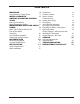
CONTENTS WARNINGS 4 Pay Attention to These Terms 4 WATER CHEMISTRY 5 OWNER'S OPERATING INSTRUCTIONS 6 Start-Up Procedures 6 Water Temperature Safety 9 MAINTENANCE AND CARE PROCEDURES 9 Basic Tips if Heater Will Not Fire 9 Pool & Spa Water Chemistry 10 Cold Weather Operation 10 Winterizing the Spa Heater 10 INTRODUCTION 10 Receiving Equipment 10 General Specifications 11 INSTALLATION 11 Code Requirements 11 Base Installation 11 Clearances Outdoor Heaters Indoor Heaters Combustion Air (Indoor Units Only) Ven
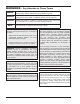
WARNINGS - Pay Attention to These Terms DANGER: Indicates the presence of immediate hazards which will cause severe personal injury, death or substantial property damage if ignored. WARNING: Indicates the presence of hazards or unsafe practices which could cause severe personal injury, death or substantial property damage if ignored. CAUTION: Indicates the presence of hazards or unsafe practices which could cause minor personal injury or product or property damage if ignored.
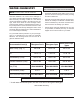
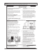
WATER CHEMISTRY CAUTION: Free chlorine must not exceed 5 ppm which can damage the heater and void the warranty. NOTE: Corrosive water voids all warranties. Chemical imbalance can cause severe damage to your heater and associated equipment. Maintain your water chemistry according to Table A. If the mineral content and dissolved solids in the water become too high, scale forms inside the heat exchanger tubes, reducing heater efficiency and damaging the heater. If the pH drops below 7.
OWNER'S OPERATING INSTRUCTIONS After Start-Up Feel the inlet and outlet pipes. Outlet pipe should be only slightly warmer than the inlet. It should not be hot. WARNING: If you do not follow these instructions exactly, a fire or explosion may result, causing property damage, personal injury or loss of life. WARNING: Should overheating occur or the gas supply fail to shut off, turn off the manual gas control to the appliance.
CAUTION: Propane is heavier than air and will settle on the ground. Since propane can accumulate in confined areas, extra care should be exercised when lighting propane heaters. LIGHTING INSTRUCTIONS AND SHUT-OFF PROCEDURES MANUALLY LIGHTED PILOTS (MILLIVOLT SYSTEM) A. This appliance has a pilot that must be lighted by hand. When lighting the pilot, follow these instructions exactly. *If you cannot reach your gas supplier, call the fire department. C.
CAUTION: Propane is heavier than air and will settle on the ground. Since propane can accumulate in confined areas, extra care should be exercised when lighting propane heaters. OPERATING INSTRUCTIONS AND SHUT-OFF PROCEDURES AUTOMATICALLY LIGHTED PILOTS (ELECTRONIC IGNITION SYSTEMS) A. This appliance is equipped with an ignition device which automatically lights the pilot. Do not try to light the pilot by hand. *If you cannot reach your gas supplier, call the fire department. C.
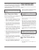
MAINTENANCE AND CARE PROCEDURES valve when water flow to the heater is interrupted. Otherwise, rapid and severe heater damage will likely occur. (The water pressure switch should be checked and adjusted for proper operation by a qualified service person at the time of installation and periodically checked thereafter. Refer to pressure switch servicing instructions in this manual.) To be followed one month after start-up and then semiannually. 1.
If you have electrical power, check the following: water below 50°F can seriously damage the heater, and will void the warranty. 1. The time clock must be moved to the "ON" position. For cold climate areas please follow the winterizing procedures listed below. 2. Your pump strainer basket may be full. If so remove debris. Winterizing the Spa Heater 3. Your filter may be dirty. If so, backwash or clean filter. (If your filter is dirty, the gauge pressure will be higher than usual).
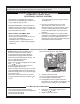
General Specifications WARNING: Improper installation, adjustment, alteration, service or maintenance may damage the equipment, create a hazard resulting in asphyxiation, explosion or fire, and will void the warranty. These heaters are design certified and tested under the requirements of ANSI Z21.56/CSA 4.7 American National Standard / CSA standards for gas-fired pool heaters. Code Requirements The heater is interchangeable and can be used either indoors or outdoors.
Indoor Installation Outdoor Installation Heater Side Min. Clearance from Combustible Surfaces Heater Side Min.
Indoor Heaters from or one (1) foot above any door, window or gravity inlet to a building. The top surface of the heater shall be at least three (3) feet above any forced air inlet, or intake ducts located within ten (10) feet horizontally. The design is also certified for indoor installation when equipped with the approved drafthood. For Canada, indoor installation is restricted to an enclosure that is not occupied and does not directly communicate with occupied area.
Vent Terminal Assembly Vent Piping Outdoor WARNING: Indoor boilers require a drafthood that must be connected to a vent pipe and properly vented to the outside. Failure to follow this procedure can cause fire or fatal carbon monoxide poisoning. 1. Remove the (4) screws which fasten jacket top to heater. 2. Lower outdoor top onto unit lining up slots in outdoor top with screw holes in jacket top.
Type "B" double wall or equivalent vent pipe is recommended. However single-wall metal vent pipe may be used as specified in the latest edition of the National Flue Gas Code ANSI Z223.1 (Canada-CAN/CGA B149). 10' OR LESS CAUTION: The heater and its manual shut-off valve must be disconnected from the gas supply during any pressure testing of that system at test pressures in excess of 1/2 psig (3.45 kPa).
Gas Pressure Adjustment Gas Pressure Test at Heater Gas Pressure Test at Gas Valve Fig. 11: Gas Pressure Testing Locations Fig. 14: Honeywell IID Valve Gas Pressure Adjustment Plumbing for Water Connections Location The VERSA heater requires water flow and positive pressure to fire and operate properly. It must therefore be installed downstream of the discharge side of the filter pump. A typical installation is plumbed as follows: 1.
Flow Rates Pipe Size Min. gpm Max. gpm 1-1/4” 20 60* 1-1/2” 20 60* Automatic Chlorinators and Chemical Feeders All chemicals must be introduced and completely diluted into the pool or spa water before being circulated through the heater. Do not place chlorine tablets or bromine sticks in the skimmer. High chemical concentrations will result when the pump is not running (e.g. overnight). *When flow rates exceed 60 gpm, an external auxiliary bypass valve is required.
External Auxiliary Bypass Valve (Where Required) NOTE: To avoid water damage or scalding due to valve operation, drain pipe must be connected to valve outlet and run to a safe place of discharge. Drain pipe must be the same size as the valve discharge connection throughout its entire length and must pitch downward from the valve. No shut-off valve shall be installed between the relief valve and the drain line. Valve lever should be tripped at least once a year to ensure that waterways are clear.
240V ATMOSPHERIC HEATER HOT L1 SUPPLY SIDE BLACK BLACK HOT S L2 Robertshaw Intermittent Ignition Device RED RED GREEN GREEN Honeywell Intermittent Ignition Device WHITE Fig. 21: 240V Wiring Fig. 19: Intermittent Ignition Devices For 120 V input power to the unit, connect the black wire to the “L1”, or hot leg, of the power supply. Connect the white wire to the “L2”, or neutral leg, of the power supply. Attach the wire nut to the red wire.
Wiring Diagram—Millivolt Units with Mechanical Thermostat 20
Wiring Diagram—IID Units BL BL BL 21
SERVICE The thermostat is fitted with a means of limiting the upper temperature limit below the maximum level. The knob stop adjustment ring illustrated above is adjustable by loosening the set screw, rotating the knobstop ring to the desired location and retightening the set screw. Controls/Adjustments/ Replacements DANGER - SHOCK HAZARD - Make sure electrical power to the heater is disconnected to avoid potential serious injury or damage to components.
Pressure Switch NOTE: If heater is installed outside of the limits shown, a flow switch must be used in place of the pressure switch when mounted and wired adjacent to the heater. The pressure switch, or heater actuator, ensures that the heater operates only when the filter pump is in operation. It is factory set at 1.75 PSI for deck level installations.
Main Burner and Orifice Removal NOTE: An erratic high limit is often characteristic of internal heat exchanger problem, e.g. scale build-up, U.G. operation. Refer to Troubleshooting section. 1. Remove burner tray. (See Burner Tray Removal procedure). 2. Remove screws and burner hold-down bracket.
Heat Exchanger Removal 1. Shut water, gas, and electricity off, close valves and relieve pressure. 2. Drain heat exchanger. 3. Loosen and remove flange bolts. 4. Remove flange and inlet/outlet pipes from the header. Remove drain valve from rear header. 5. Remove outdoor stackless top or indoor stack top from unit. 6. Remove jacket top, flue collector, and baffle. 7. Remove upper front jacket panel, and disconnect wires at toggle switch. 8. Remove capillary bulb from inlet/outlet header. 9.
U.G. U.G. Shield Retainer Spring Outlet Inlet Inlet/Outlet Header Fig. 31: Unitherm Governor Location To test the operation of the Unitherm Governor, place in hot water (over 110°F) and watch for movement against spring. If there is no movement, replace unit.
TROUBLESHOOTING These instructions are primarily intended for use by qualified personnel specifically trained and experienced in the installation of this type of heating equipment and related system components. Installation and service personnel may be required by some states to be licensed. Persons not qualified shall not attempt to install this equipment nor attempt repairs according to these instructions. MECHANICAL PROBLEM Harmonics, or whining noise CAUSE SOLUTION U.G. inoperative.....................
Liming Bypassing too much water............ Inspect bypass for movement, if no movement, replace. U.G. not functioning...................... Replace if no movement when heated. Leaking at well Overacid.................................. Leaking at heat exchanger Overacid.................................. Gasket brittle and leaking (overheated) Heater running after pump shuts off................................... Refractory damage..................... Sooted heater............................
WARNING HIGH VOLTAGE For qualified Technicians ONLY ELECTRICAL - IID Intermittent Pilot System TROUBLESHOOTING HONEYWELL S8600 START TURN GAS SUPPLY OFF. TURN THERMOSTAT (CONTROLLER) TO CALL FOR HEAT POWER TO MODULE (24 V NOMINAL)? YES SPARK ACROSS IGNITER/SENSOR GAP? YES NOTE: Some heaters may be equipped with an ignition module that shuts off pilot gas if pilot fails to light. To reset, interrupt power to heater.
ELECTRICAL - IID, SOLID STATE THERMOSTAT If the pool/spa/hot tub water is too cold, troubleshoot the system as follows: Check voltage at 24 V terminals. VOLTAGE BETWEEN 21.5-28.5 V. Set control to max. temperature. After 2-3 cycles, check water temperature. VOLTAGE OUTSIDE RANGE 21.5-28.5 V. Check transformer, 120 V supply, correct as necessary TEMPERATURE BELOW 105°F Disconnect sensor leads from circuit board. Measure sensor resistance with ohmmeter. TEMPERATURE 105-106° F. Control ok.
REPLACEMENT PARTS LIST serial number, model number, etc., and shipped to the Company freight prepaid. If determined defective by the Company and within warranty, the part will be returned in kind or equal substitution, freight collect. Credit will not be issued. In order to receive the correct part it is important that you state the model number, serial number and type of gas when applicable.
1-S 7-C 1-V 2-V 2-S 3-H 12-H 5-H 6-H 8-H 1-C 10-H 2-C 13-H 4-H 7-H 2-H 4-S 1-R 5-M 14-H 3-S 11-H 7-M 4-M 3-M 6-C 2-M 1-B 1-M 5-S 5-C 6-M 3-C Fig # 240654 1-G 4-C 2-B 3-B 11-P 9-M HONEYWELL IID PILOT HONEYWELL MILLIVOLT PILOT 1-P 9-P 3-P 12-P 13-P 5-P 15-P 14-P 7-P 14-P Fig # 8133 Fig # 8132 32 6-S
CALL OUT B 1-B 2-B 3-B DESCRIPTION BURNER TRAY Burner Tray w/Burners (Sea Level)* Burner Burner Orifice Nat. #52 (Sea Level)* Burner Orifice Pro. #62 (Sea Level)* C CONTROLS 1-C High Limit 135 F 2-C High Limit 140 F 3-C Thermostat Control MV (Mechanical) 8-C Thermostat Control MV (Solid State) 5-C PC Board 6-C Potentiometer 7-C Temperature Sensor 9-C Thermostat Control IID (Solid State) 4-C PC Board 6-C Potentiometer 7-C Temperature Sensor G GAS VALVE 1-G Combination Valve Nat. MV Combination Valve Pro.
CALL OUT P 1-P 3-P 5-P 7-P 9-P 11-P 12-P 13-P 15-P R 1-R S 1-S 2-S 3-S 4-S 5-S 6-S V 1-V 2-V DESCRIPTION PILOT Pilot Nat. MV Pilot Pro. MV Pilot Nat. IID Pilot Pro. IID Pilot Orifice Nat. MV Pilot Orifice Pro. MV Pilot Orifice Nat. IID Pilot Orifice Pro. IID Pilot Generator MV Ignition Control IID Nat. Ignition Control IID Pro.