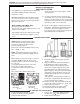
www.SpaDepot.com CATALOG NO. 6100.52S Effective: 01-16-07 Replaces: 10-24-05 INSTALLATION AND OPERATING INSTRUCTIONS VERSA SPA HEATER Model 055B WARNING: If the information in these instructions is not followed exactly, a fire or explosion may result causing property damage, personal injury or death. — Do not store or use gasoline or other flammable vapors and liquids in the vicinity of this or any other appliance. — WHAT TO DO IF YOU SMELL GAS • Do not try to light any appliance.
Contents 4 PART ONE - Owner's Operating Instructions 4 4 5 7 SECTION 1 / START-UP PROCEDURES Before Start-Up Lighting Instructions & Shut-Off Procedures (manually lighted MILLIVOLT pilot) Operating Instructions & Shut-Off Procedures (automatically lighted IID pilot ) After Start-Up 7 SECTION 2 / CAUTION 7 8 8 SECTION 3 / MAINTENANCE & CARE PROCEDURES Pool & Spa Water Chemistry Winterizing the Pool and Spa Heater 9 PART TWO - Installation / Service Instructions 9 SECTION 1 / RECEIVING EQUIPMENT
PART ONE - OWNER'S OPERATING INSTRUCTIONS FOR YOUR SAFETY - READ BEFORE OPERATING WARNING: IF YOU DO NOT FOLLOW THESE INSTRUCTIONS EXACTLY, A FIRE OR EXPLOSION MAY RESULT, CAUSING PROPERTY DAMAGE, PERSONAL INJURY OR LOSS OF LIFE. SECTION 1 / START-UP PROCEDURES BEFORE START-UP BURNERS Clean main burners and air louvers of dust, lint and debris. Keep heater area clear and free from combustibles, flammable liquids and chemicals. Do not obstruct the flow of combustion and ventilation air.
CAUTION: Propane is heavier than air and will settle on the ground. Since propane can accumulate in confined areas, extra care should be exercised when lighting propane heaters. LIGHTING INSTRUCTIONS AND SHUT-OFF PROCEDURES MANUALLY LIGHTED PILOTS (MILLIVOLT SYSTEM) A. This appliance has a pilot that must be lighted by hand. When lighting the pilot, follow these instructions exactly. *If you cannot reach your gas supplier, call the fire department. C.
CAUTION: Propane is heavier than air and will settle on the ground. Since propane can accumulate in confined areas, extra care should be exercised when lighting propane heaters. OPERATING INSTRUCTIONS AND SHUT-OFF PROCEDURES AUTOMATICALLY LIGHTED PILOTS (ELECTRONIC IGNITION SYSTEMS) A. This appliance is equipped with an ignition device which automatically lights the pilot. Do not try to light the pilot by hand. *If you cannot reach your gas supplier, call the fire department. C.
AFTER START-UP SECTION 2 / CAUTION Feel the inlet and outlet pipes. Outlet pipe should be only slightly warmer than the inlet. It should not be hot. Elevated water temperature can be hazardous, and the U.S. Consumer Product Safety Commission recommends the following guidelines: WARNING: Should overheating occur or the gas supply fail to shut-off, turn off the manual gas control valve to the appliance. 1. Spa or hot tub water temperatures should never exceed 104°F (40°C).
4. Make visual check of the burner and pilot flame. Flame pattern on the main burner and pilot is indicated in the previous illustration. Yellow flame means restriction of the air openings. Lifting or blowing flame indicates high gas pressure. Low flame means low gas pressure. Should this occur, shut the heater off and contact your gas supplier or qualified service agency. 5. On indoor heaters, clean room intake openings to ensure adequate flow of combustion and ventilation air.
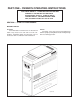
PART 2 - INSTALLATION / SERVICE INSTRUCTIONS SECTION 1 / RECEIVING EQUIPMENT SECTION 3 / INSTALLATION INSTRUCTIONS On receipt of your equipment it is suggested that you visually check for external damage to the carton. If the carton is damaged, a note should be made on the Bill of Lading when signing for the equipment. Remove the heater from the carton and if it is damaged, report the damage to the carrier immediately. On occasion, we ship some items loose.
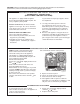
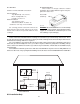
ALL HEATERS OUTDOOR HEATERS These heaters are design certified for outdoor installation, when equipped with the approved top designated for outdoor use. Clearances from Combustible construction: Indoor Installation Top* (Drafthood) - 35"; Vent - 6"; Back - 2"; Right Side - 6"; Left Side - 6"; Floor - 0 Outdoor Installation Top* (Stackless Top) unobstructed; Back - 2"; Sides - 6" * Clearance from Top of Vent Terminal Heater with outdoor top Fig.
HIGH WIND CONDITIONS (OUTDOOR UNITS ONLY) In areas where high winds are frequent, it may be necessary to locate the heater a minimum of 3' from high vertical walls, or install a wind break so the heater is not in direct wind current. VENTING CONNECTIONS VENT TERMINAL ASSEMBLY Outdoor STEP 1: Remove the (4) screws which fasten jacket top to heater. STEP 2: Lower outdoor top onto unit lining up slots in outdoor top with screw holes in jacket top.
VENT PIPING WARNING: Indoor boilers require a drafthood that must be connected to a vent pipe and properly vented to the outside. Failure to follow this procedure can cause fire or fatal carbon monoxide poisoning.
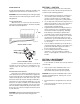
GAS SUPPLY CONNECTIONS Gas piping must have a sediment trap ahead of the heater gas controls, and a manual shut-off valve located outside the heater jacket. All gas piping should be tested after installation in accordance with local codes. Fig. # 9421 Fig. # 9420 CAUTION: The heater and its manual shut-off valve must be disconnected from the gas supply during any pressure testing of that system at test pressures in excess of 1/2 psig (3.45 KPA).
PLUMBING FOR WATER CONNECTIONS LOCATION The VERSA heater requires water flow and positive pressure to fire and operate properly. It must therefore be installed downstream of the discharge side of the filter pump. A typical installation is plumbed as follows: 1. The inlet side of the filter is plumbed directly to the discharge side of the filter pump: 2. The outlet side of the filter is then plumbed to the inlet of the heater; and 3. The outlet of the heater is plumbed to the return line to the spa.
throughout its entire length and must pitch downward from the valve. No shut-off valve shall be installed between the relief valve and the drain line. Valve lever should be tripped at least once a year to ensure that waterways are clear. EXTERNAL AUXILIARY BYPASS VALVE (Where required) An auxiliary bypass valve should be used when flow rates exceed 60 GPM (usually a high performance pump size larger than 1-1/2 HP will exceed this flow rate).
For 120 V input power to the unit, connect the black wire to the “L1”, or hot leg, of the power supply. Connect the white wire to the “L2”, or neutral leg, of the power supply. Attach the wire nut to the red wire. There should be no connection to the red wire for 120V operation. WIRING DIAGRAM KEY PINK CONNECTOR BLUE CONNECTOR Fig. #9240 For 240 V input power to the unit, connect the black wire to the “L1”, or hot leg, of the power supply.
WIRING DIAGRAMS MILLIVOLT UNITS WITH MECHANICAL THERMOSTAT If required by local code, install at this location. Fig.
WIRING DIAGRAM IID UNITS BL BL BL 18
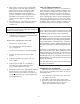
SECTION 4 / SERVICING INSTRUCTIONS GENERAL LOCATION OF CONTROLS Drain Valve HIGH LIMITS (Located in the Inlet/Outlet header) Pressure Switch Burner & Pilot Thermal Fuse Solid State Thermostat & Ignition Control Gas Valve Fig. # 8160.1s CONTROLS/ADJUSTMENTS/REPLACEMENTS CAUTION: Label all wires prior to disconnection when servicing controls. Wiring errors can cause improper and dangerous operation. Verify proper operation after servicing.
PRESSURE SWITCH ADJUSTMENT: FLAME ROLL-OUT SAFETY SWITCH 1. With pump and heater on, turn adjustment knob (clockwise) until a click is heard from the gas valve. 2. Turn adjustment knob (counter-clockwise) 1/4 turn. 3. Turn pump off and on several times. Heater should shut-off immediately. If it does not, repeat steps above until proper adjustment is made. The heater is equipped with a thermal cut-off device to prevent flame roll-out in the event the heat exchanger becomes blocked.
BURNER TRAY REMOVAL 1. Shut-off main electrical power switch to heater. 2. Shut-off gas upstream of heater. 3. Remove front door. 4. Disconnect gas line from gas valve. 5. Remove (2) screws that mount burner tray to unit. 6. Disconnect wires that terminate at gas valve, and thermal fuse. 7. Slide out burner tray. 8. Reverse above procedure to reinstall. Pilot Pilot Air Opening GAS VALVE REMOVAL 1. Remove burner tray. (See Burner Tray Removal procedure). 2. Disconnect pilot tubing from gas valve. 3.
DESOOTING PROCEDURE CONTROL IMMERSION WELL REPLACEMENT 1. Remove plumbing and top portion of unit (See Heat Exchanger Removal procedure, steps 1 through 6). 2. Remove U.G. spring, U.G. and copper shield. 3. Collapse well tube at open end with chisel. 4. Push well up through header. 5. Insert new well and roll in place. If a roller is not available, solder the well in place with silver solder. CAUTION: SOOT IS COMBUSTIBLE. EXERCISE EXTREME CARE. NEVER USE A WIRE BRUSH.
SECTION 5 / TROUBLESHOOTING GUIDE IMPORTANT NOTICE These instructions are primarily intended for use by qualified personnel specifically trained and experienced in the installation of this type of heating equipment and related system components. Installation and service personnel may be required by some states to be licensed. Persons not qualified shall not attempt to install this equipment nor attempt repairs according to these instructions.
Liming Bypassing too much water............ Inspect bypass for movement, if no movement, replace. U.G. not functioning...................... Replace if no movement when heated. Leaking at well Overacid.................................. Leaking at heat exchanger Overacid.................................. Gasket brittle and leaking (overheated) Heater running after pump shuts off................................... Refractory damage..................... Sooted heater............................
WARNING HIGH VOLTAGE For qualified Technicians ONLY ELECTRICAL - IID Intermittent Pilot System TROUBLESHOOTING HONEYWELL S8600 START TURN GAS SUPPLY OFF. TURN THERMOSTAT (CONTROLLER) TO CALL FOR HEAT POWER TO MODULE (24 V NOMINAL)? YES NOTE: Some heaters may be equipped with an ignition module that shuts off pilot gas if pilot fails to light. To reset, interrupt power to heater. NOTE: Before troubleshooting, familiarize yourself with the start-up and checkout procedure.
ELECTRICAL - IID, SOLID STATE THERMOSTAT If the pool/spa/hot tub water is too cold, troubleshoot the system as follows: Check voltage at 24 V terminals. VOLTAGE BETWEEN 21.5-28.5 V. Set control to max. temperature. After 2-3 cycles, check water temperature. VOLTAGE OUTSIDE RANGE 21.5-28.5 V. Check transformer, 120 V supply, correct as necessary TEMPERATURE BELOW 105°F Disconnect sensor leads from circuit board. Measure sensor resistance with ohmmeter. TEMPERATURE 105-106° F. Control ok.
SECTION 6 / REPLACEMENT PARTS LIST If determined defective by the Company and within warranty, the part will be returned in kind or equal substitution, freight collect. Credit will not be issued. NOTE: In order to receive the correct part it is important that you state the model number, serial number and type of gas when applicable.
1-S 7-C 2-V 2-S 1-V 3-H 12-H 5-H 6-H 8-H 1-C 10-H 2-C 13-H 4-H 7-H 4-S 2-H 1-R 5-M 14-H 3-S 11-H 7-M 4-M 3-M 6-C 1-B 2-M 1-M 5-S 5-C 6-M 3-C Fig # 240654 1-G 4-C 2-B 3-B 11-P 9-M HONEYWELL IID PILOT HONEYWELL MILLIVOLT PILOT 1-P 9-P 3-P 12-P 13-P 7-P 5-P 15-P 14-P 14-P Fig # 8133 Fig # 8132 28 6-S
PART NUMBER 30