INSTALLATION & OPERATING INSTRUCTIONS ULTRA HIGH EFFICIENCY Models 1005–2005 Types H, WH & WHP L W WARNING: Improper installation, adjustment, alteration, service or maintenance can cause property damage, personal injury, exposure to hazardous materials* or loss of life. Review the information in this manual carefully. *This unit contains materials that have been identified as carcinogenic, or possibly carcinogenic, to humans.
CONTENTS WARNINGS Pay Attention to These Terms BEFORE INSTALLATION Product Receipt Model Identification Ratings and Certifications Installations at Elevation Component Locations General Information Time/Temperature Relationships in Scalds GENERAL SAFETY INSTALLATION Installation Codes Equipment Base Clearances Combustion and Ventilation Air Conventional Combustion Air Supply Water Piping Hydronic Heating Gas Supply Electrical Power Connections Field Wiring Connection Venting Venting Installation Tips Ventin
WARNINGS Pay Attention to These Terms DANGER: Indicates the presence of immediate hazards which will cause severe personal injury, death or substantial property damage if ignored. WARNING: Indicates the presence of hazards or unsafe practices which could cause severe personal injury, death or substantial property damage if ignored. CAUTION: Indicates the presence of hazards or unsafe practices which could cause minor personal injury or product or property damage if ignored.
BEFORE INSTALLATION the upper rear jacket panel of the heater. The model number will have the form H7-2005 or similar depending on the heater size and configuration. The letter(s) in the first group of characters identifies the application (H = Hydronic Heating, WH = Domestic Hot Water (DHW), WHP = Water Heater for Pool Heating). The number which follows identifies the firing mode (7 = electronic modulation, 1 = On/Off).
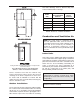
Component Locations Fig. 1: Component Locations – Right Side Fig. 3: Component Locations – Rear General Information Model No. MBTUH Input Water Conn. (NPT) Max. Min. Gas Conn. (NPT) N P 6 Flue Intake 1005 999 250 2-1/2 1-1/4 1 6 6 1505 1500 375 2-1/2 1-1/4 1 8 8 2005 1999 500 2-1/2 2 1 8 8 Table A: Basic Data Fig. 2: Component Locations – Top Vent Size (in.
GENERAL SAFETY To meet commercial hot water use needs, the high limit safety control on this water heater will shut off the main gas valve before the outlet temperature reaches 210°F. However, water temperatures over 125°F can cause instant severe burns or death from scalds. When supplying general purpose hot water, the recommended initial setting for the temperature control is 125°F. Safety and energy conservation are factors to be considered when setting the water temperature on the thermostat.
Equipment Base The temperature of the water in the heater can be regulated by using the Raypak Modulating Temperature Control. To comply with safety regulations, the control is set at 120°F when shipped from the factory (Mode 3 default setting for Tank Target). The heater should be mounted on a level, structurally sound surface. The heater is approved for installation on a combustible surface but must NEVER be installed on carpeting.
Roof water drainage must be diverted away from heaters installed under overhangs. Heater Side Min.
Fig. 6: Minimum Clearances from Vent/Air Inlet Terminations – Indoor and Outdoor Installations 1 1 2 t TT * 2 U.S. Installations Canadian Installations A Clearance above grade, veranda, porch, deck, or balcony 1 ft (30 cm) 1 ft (30 cm) B Clearance to window or door that may be opened 4 ft (1.
Combustion Air Filter Inside Air Intake Cover Panel This heater is supplied with an integral combustion air filter. This filter will reduce the amount of particulates passed through the combustion system and heat exchanger but will not protect against chemical inside air contamination (See Appendix). The filter must be checked periodically to verify that adequate combustion air is being supplied to the heater.
8. Remove the debris screen (or cover panel for model 1005) by removing the six screws holding it in place. 12. Provide adequate ventilation of the space occupied by the heater(s) by an opening(s) for ventilation air at the highest practical point communicating with the outdoors. The total cross-sectional area shall be at least 1 in.
2. One permanent opening, commencing within 12 in. (305 mm) of the top of the enclosure, shall be permitted where the equipment has clearances of at least 1 in. (25 mm) from the sides and back and 6 in. (152 mm) from the front of the appliance. The opening shall directly communicate with the outdoors or shall communicate through a vertical or horizontal duct to the outdoors or spaces that freely communicate with the outdoors, and shall have a minimum free area of: Conventional Combustion Air Supply U.S.
The heater is supplied with a Section IV “HV” stamped relief valve sized for the full input of the unit. The relief valve assembly is shipped loose and must be mounted directly to the heater outlet. No valve shall be installed between the heater and the relief valve. The relief valve shall be mounted with its spindle vertical (see Fig. 1, 2 and 3 on page 6).
Feedwater Regulator Leaks must be repaired at once to prevent damage to the heater. NEVER use petroleum-based stop-leak compounds. Raypak recommends that a feedwater regulator be installed and set at 12 psi minimum pressure at the highest point of the system. Install a check valve or back flow device upstream of the regulator, with a manual shut-off valve as required by local codes. To perform hydrostatic test: 1. Connect fill water supply. With bleed valve open, fill heater with water.
Model 2005 System Model 1505 Model 1005 Supply Temp1 Minimum Pipe Size2 Minimum Pipe Size2 Minimum Pipe Size2 Supply Temp1 Return Temp Supply Temp1 (°F) (°F) <80' equiv. 80-200' equiv. (°F) <80' equiv. 80-200' equiv. (°F) <80' equiv. 80-200' equiv.
NOTE: If local codes require a vacuum relief valve, acquire one locally and install per valve manufacturer’s instructions. CAUTION: Power to the heater should be interlocked with the main system pump to make sure the heater does not fire without the main system pump in operation. Improper flow control can damage the heater. Uncontrolled flow (too high) or restricted flow (too low) can seriously damage the heater. Follow these instructions to make sure the heater is properly installed.
Model 2005 Model 1505 Model 1005 Tank Minimum Tubing Size2 Hard Sup. S oft/M ed Minimum Tubing Size2 Minimum Tubing Size2 Return Temp Soft/Med Sup. Hard Sup. Soft Sup. Med Sup. Temp1 (°F) Temp1 (°F) Temp1 (°F) <80' equiv. 80-200' equiv. Temp1 (°F) Temp1 (°F) (°F) <80' equiv. 80-200' equiv. Sup. Temp1 (°F) <80' equiv. 80-200' equiv.
Occasional chemical shock dosing of the pool or spa should not damage the heater providing the water is balanced. of the heater gas controls. Refer to Table K on page 20 for maximum pipe lengths. Gas Supply Connection Automatic chemical dosing devices and salt chlorinators are usually more efficient in heater water, unless controlled, they can lead to excessive chlorine level which can damage your heater.
1-1/4” NPT 1-1/2” NPT N P N P N P N 1005 35 55 35 90 125 300 300 1505 10 15 15 25 60 150 150 275 35 90 85 210 Model No. 2” NPT 2005 2-1/2” NPT P Natural Gas – 1,000 BTU/ft3, 0.60 specific gravity at 0.5 in. WC pressure drop Propane Gas – 2,500 BTU/ft3, 1.53 specific gravity at 0.6 in. WC pressure drop Table K: Maximum Equivalent Pipe Length Gas Supply Pressure • • A minimum of 4.0 in. WC and a maximum of 10.5 in.
WARNING: Using a multi-meter, check the following voltages at the circuit breaker panel prior to connecting any equipment. Make sure proper polarity is followed and house ground is proven. (See Fig. 20.) Check the power source: AC = 108 VAC Minimum, 132 VAC MAX AB = 108 VAC Minimum, 132 VAC MAX BC = <1 VAC Maximum Fig.
temperature that avoids excessive condensate production in the vent. NOTE: A grounding electrode conductor shall be used to connect the equipment grounding conductors, the equipment enclosures, and the grounded service conductor to the grounding electrode. Category II – A heater which operates with a non-positive vent static pressure and with a vent gas temperature that may cause excessive condensate production in the vent.
Combustion Air Supply Exhaust Configuration Heater Venting Category Certified Materials IV CAT IV AL29-4C Vertical Venting From Inside Building (Non-Direct Venting) Horizontal Throughthe-Wall Venting Vertical Venting From Outside Building (Direct Venting) Horizontal Throughthe-Wall Venting Combustion Air Inlet Material Galvanized Steel PVC ABS CPVC Table M: Venting Category Requirements from combustible materials.
5. Terminate vent at least 6 ft away from adjacent walls. 8. Underneath a verandah, porch or deck, unless the verandah, porch or deck is fully open on a minimum of two sides beneath the floor, and the distance between the top of the vent termination and the underside of the verandah, porch or deck is greater than 1 ft (305 mm). 6. DO NOT terminate vent closer than 5 ft below roof overhang. 7. The vent terminal requires a 12 in. vent terminal clearance from the wall. Venting Installation Tips 8.
Model No. Certified Vent Material 1005 1505 Vent Size (in.) Vertical Vent Height1 (ft) Min. Max. 6 Category IV (AL29-4C) 0 75 8 2005 Combustion Air Intake Pipe Material Galvanized Steel, PVC, ABS, CPVC Air Inlet Max. Length* (ft) 6” Ø 8” Ø 45 100** 1 Vent lengths are based on a lateral length of 2 ft. Refer to the latest edition of the NFGC for further details. * Subtract 10 ft per elbow. Max. 4 elbows. ** Adapters supplied by others. Table N: Category IV Vertical Venting nal.
CAUTION: A listed vent cap terminal suitable for connection to the Cat IV vent materials, adequately sized, must be used to evacuate the flue products from the heaters. NOTE: For extractor sizing, typical CO2 levels are 8.5% for natural gas and 9.5% for propane gas and flue temperature of 150° F. Common Venting The NFGC does not address sizing guidelines for the common venting of multiple Category IV heaters. This is covered in the NFGC under “Engineered Vent Systems”.
Horizontal Through-the-Wall and Direct Venting (Category IV) Fig. 27: Horizontal Through-the-Wall Direct Venting Fig. 25: Horizontal Through-the-Wall Venting CAUTION: This venting system requires the installation of a condensate drain in the vent piping per the vent manufacturer’s instructions. Failure to install a condensate drain in the venting system will void all warranties on this heater.
Model No. Certified Vent Material Vent Size (in.) 1005 Horizontal Vent Length (ft) Min. Max. Combustion Air Intake Pipe Material 0 6” Ø 8” Ø 45 100** Galvanized Steel, PVC, ABS, CPVC 6 Category IV (AL29-4C) Air Inlet Max. Length* (ft) 75 1505 8 45 10” Ø 85** 2005 * Subtract 10 ft per elbow. Max. 4 elbows. ** Adapters supplied by others. Table P: Category IV Horizontal Vent & Horizontal Direct Vent Direct Vent—Vertical The vent must be installed to prevent flue gas leakage.
Outdoor Installation in any arrangement that does not exceed the lengths shown in Tables N and P. The vent cap is not considered in the overall length of the venting system. XTherm heaters are certified for outdoor operation in non-freezing conditions only. Freezing conditions may cause condensate to freeze in the condensate drain line and trap causing the unit to shut down from a blocked condensate drain. Additionally, components of the condensate management system may be damaged by the ice formation.
NOTE: The vent cap and air intake hood must be furnished by the heater manufacturer in accordance with its listing (sales order option D-11). CAUTION: This appliance has provisions to be connected to more than one supply source. To reduce the risk of electric shock, disconnect all such connections before servicing. NOTE: Condensate can freeze on the vent cap. Frozen condensate on the vent cap can result in a blocked flue condition.
Operating Modes Mode 4 – Not recommended. Mode 1 – Not recommended. Mode 5 – Outdoor reset using primary/secondary piping. The heater is operated as in Mode 2. However, the target temperature is based on outdoor reset. See Fig. 33. Mode 2 – Setpoint operation using primary/secondary piping. The control operates the heater to satisfy a remote system sensor. The heater is turned off based on boiler max and boiler differential (factory default). See Fig. 31.
MODULATING 2-10 VDC 4-20 mA* Boiler Target 0 0 --- (OFF) 1 2 --- (OFF) 2 4 50°F 3 6 71.3°F 4 8 92.5°F 5 10 113.8°F 6 12 135°F 7 14 156.3°F 8 16 177.5°F 9 18 198.8°F 10 20 220°F *Requires a 500Ω resistor. Table R: 2-10 VDC or 4-20 mA External Input Signal * *Maximum 4 times the pipe diameter or 12”, whichever is less. Fig. 34: Mode 7 Primary/Secondary Piping with External Target Temp 0-10 VDC 0-20 mA* Boiler Target 0 0 --- (OFF) 1 2 50°F 2 4 68.
Item Modes Default Setting Range 1, 2 160°F OFF, 70 to 220°F 3 160°F OFF, 70 to 190°F 4, 5, 6, 7 180°F OFF, 70 to 220°F 1, 2, 4, 5, 6, 7, 8 200°F OFF, 120 to 225°F 3 180°F OFF, 120 to 190°F Boil Min 1, 2, 3, 4, 5, 6, 7 150°F OFF, 80 to 180°F ‘Burner’ Delay All 0:00 min 0:00 to 3:00 min Boil Mass All 1 (Low) 1 (Low), 2 (Med), 3 (High) Diff 1, 2, 3, 4, 5, 6, 7 Auto Auto, 2 to 42°F DHW Target 3 120°F OFF, 70 to 190°F DHW Diff 3 5°F 2 to 10°F ‘Pump’ Dly All 3:00 min
Definitions 0-10VDC or 0-20 mA external input signal – When the 0-10VDC signal is selected, an input voltage of 1 VDC corresponds to a boiler target temperature of 50°F (10°C). An input voltage of 10 VDC corresponds to a boiler target temperature of 220°F (104°C). As the voltage varies between 1 VDC and 10 VDC, the boiler target temperature varies linearly between 50°F (10°C) and 220°F (104°C). If a voltage below 0.
Rank Item Field Number Field Type Fault Description 0 E01 Err Error EEPROM error 1 FP Err Warning Flame proof warning 2 BOIL OUT SHr Error Boiler outlet sensor short 3 BOIL OUT OPn Error Boiler outlet sensor open 4 BOIL IN SHr Error Boiler inlet sensor short 5 BOIL IN OPn Error Boiler inlet sensor open 6 SUP SHr Error System sensor short 7 SUP OPn Error System sensor open 8 OUTDR SHr Error Outdoor sensor short 9 OUTDR OPn Error Outdoor sensor open 10 D
Heater Sequence of Operation Ignition Module If all limits are satisfied and there is a call for heat: When additional heat is needed, the combustion air blower starts to purge air from the combustion chamber for 15 seconds. On proof-of-air flow, the air-proving switch closes and the igniter is energized. To ensure safe operation, the gas valve cannot open until the igniter is verified. The main burner is automatically lit when the device is powered and pre-purged.
Code Condition On System OK; No faults present Off Possible control fault; Check power 1 Flash Low air 2 Flashes Flame in combustion chamber; No call for heat 3 Flashes Ignition lockout 4 Flashes Low HSI current 5 Flashes Low 24 VAC 6 Flashes Internal fault; Replace control High Limit—Auto Reset (Optional) This heater may be equipped with an optional adjustable auto reset high limit temperature device. The optional adjustable auto reset high limit is located inside the heater junction box.
Modulating Temperature Control High & Low Gas Pressure Switches (Optional) This heater is equipped with a Raypak modulating temperature control. Refer to information starting on page 31 for information on the setting and use of this control. The optional low gas pressure switch connection mounts upstream of the gas valve (on the inlet flange to the gas valve) and is accessible through the removable access panel on the right side of the heater to reset the gas pressure switch, as necessary.
Air Pressure Switch UDB Diagnostic Board This heater is equipped with an air pressure switch to prove the operation of the blower before allowing the ignition control to begin a trial for ignition. It is located on the right side of the lower flange of the blower mounting assembly, directly behind the junction box. This heater is equipped with a diagnostic board which will indicate faults as they occur.
WIRING DIAGRAMS - Models 1005 & 1505 40
Model 2005 41
START-UP BEFORE OPERATING, smell all around the appliance area for gas. Be sure to smell near the floor because some gas is heavier than air and will settle on the floor. Pre Start-up WHAT TO DO IF YOU SMELL GAS: Filling System (Heating Boilers) • • Fill system with water. Purge all air from the system. Lower system pressure. Open valves for normal system operation, and fill system through feed pressure. Manually open air vent on the compression tank until water appears, then close vent.
Initial Start-up Required tools • • • • • • TO BURNER (1) 12-0-12 (24” scale) U-tube manometer (2) 6-0-6 (12” scale) U-tube manometer Screwdrivers (assorted sizes and shapes) (1) Crescent wrench (8” or 10”) (1) Multi-meter (1) Amp probe GAS A B C D Fig. 47: Gas Pressure Measurement Locations (Metric Allen wrenches will be required for servicing the gas valve, but not during start-up) Check Gas Supply Pressure 1. Slowly turn on main gas shut-off valve. NOTE: Digital manometers are not recommended.
Blower Check NOTE: Most commercially available amp probes are not accurate enough and/or are not shielded well enough to read accurately in the heater environment. Blower amp draw readings are for reference only. 1. Check the net blower suction using a 6-0-6 U-tube manometer by connecting one end to the blower suction pressure tee (attached to the negative side of the air pressure switch, point “A” in Fig.
Model No. Follow-Up Manifold Gas Pressure (High Fire Values) Natural Gas Propane Gas 1005 -1.1 -0.6 1505 -1.6 0.3 2005 -1.8 -2.0 Safety checks must be recorded as performed. Turn heater on. After main burner ignition: 1. Check manometer for proper readings. 2. Cycle heater several times and re-check readings. 3. Remove all manometers and replace caps and screws. Table Y: XTherm Manifold Pressure Settings CAUTION: Special manifold and air settings may be required. 4.
Post Start-Up Check dle valve to the test point B bleedle valve and open the upstream manual gas valve. Make sure that test point A & B bleedle valves have been opened so as to allow gas to flow. This will bring gas pressure to the second valve seat. Check off steps as completed: 1. Verify that the heater and heat distribution units or storage tank are filled with water. 2. Confirm that the automatic air vent (if used) was opened two full turns during the venting procedure. 3.
11. Check to see that the high limit control is set above the design temperature requirements of the system. For multiple zones: Check to make sure the flow is adjusted as required in each zone. times (one time on optional single-try ignition module). If flame is not sensed, lockout will commence. 10. If the appliance will not operate, follow the instructions “To Turn Off Gas To Appliance,” and call your service technician or gas supplier. 12. Check that the heater is cycled with the thermostat.
TROUBLESHOOTING Step 1 Does the power switch provide power to the control panel? Check the switch and/or line voltage NO Is there a Call For Heat? YES NO Unit is in standby mode. YES Step 2 NO Is Disable connection intact? Reattach. YES Step 3 Does the combustion air blower come on? Is there 120VAC at the blower or blower relay? NO Check and correct power connections at main terminal block, circuit breaker panel or blower relay.
UDB Fault History MAINTENANCE To view the fault codes in the UDB history file: Suggested Minimum Maintenance Schedule 1. Press the UP or DOWN buttons on the membrane switch for 2 seconds to access the fault history. Regular service by a qualified service agency and maintenance must be performed to ensure maximum operating efficiency. 2. Press either button to scroll through the recorded faults in history. 3.
2. Visually inspect venting system for proper function, deterioration or leakage. Ensure that condensate drain is inspected and ensure that condensate is being directed to appropriate condensate management system or drain, as required by local codes. Daily 3. Check that area is free from combustible materials, gasoline, and other flammable vapors and liquids. 3. Check burner flame. (Should see light blue flame at full input rate). 1. Check gauges, monitors and indicators. 2.
4. Conduct a combustion test at full fire. Carbon dioxide should be 8.5 to 9.0% at full fire for natural gas, and between 9.5 to 10.0% for propane gas. Carbon monoxide should be < 100 ppm. start-up. The condensate from flue gas is acidic. Combustion air can be contaminated by certain vapors in the air which raise the acidity of the condensate. Higher acidity levels attack many materials including stainless steel, which is commonly used in high efficiency systems.
Important Instructions for the Commonwealth of Massachusetts The Commonwealth of Massachusetts requires compliance with regulation 248 CMR 4.00 and 5.00 for installation of through – the – wall vented gas appliances as follows: (b) EXEMPTIONS: The following equipment is exempt from 248 CMR 5.08(2)(a)1 through 4: 1.
LIMITED PARTS WARRANTY XTHERM – TYPES H AND WH MODELS 1005-2005 SCOPE Raypak, Inc. (“Raypak”) warrants to the original owner that all parts of this heater which are actually manufactured by Raypak will be free from failure under normal use and service for the specified warranty periods and subject to the conditions set forth in this Warranty. Labor charges and other costs for parts removal or reinstallation, shipping and transportation are not covered by this Warranty but are the owner’s responsibility.
LIMITED PARTS WARRANTY XTHERM – TYPES WHP MODELS 1005-2005 SCOPE Raypak, Inc. (“Raypak”) warrants to the original owner that all parts of this heater which are actually manufactured by Raypak will be free from failure under normal use and service for the specified warranty periods and subject to the conditions set forth in this Warranty. Labor charges and other costs for parts removal or reinstallation, shipping and transportation are not covered by this Warranty but are the owner’s responsibility.
START-UP CHECKLIST FOR FAN-ASSISTED RAYPAK PRODUCTS This start-up checklist is to be completely filled out by the service technician starting up the Raypak Boiler or Heater for the first time. All information may be used for warranty purposes and to ensure that the installation is correct. Additionally this form will be used to record all equipment operation functions and required settings.
www.raypak.com Raypak, Inc., 2151 Eastman Avenue, Oxnard, CA 93030 (805) 278-5300 Fax (805) 278-5468 Litho in U.S.A.