SERVICE INSTRUCTIONS Raypak 131 Pool Heater TM020 Revision: A Published: April 09 Spartan P0131 This document is stored and maintained electronically by Service.
Contents Introduction .......................................................................................................................... 3 Safety Warning .................................................................................................................... 3 Pool Heater Model Identification .......................................................................................... 3 Specifications...........................................................................................
Introduction The information provided in these service instructions is based on the pool or spa heater being installed in accordance with AS 5601 and the Installation Instructions provided with each pool or spa heater. Should you require further technical advice on a Raypak Pool or Spa Heater, contact your nearest Rheem Service Department where genuine replacement parts are also available.
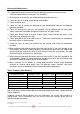
Specifications Injector size (mm) Burner Pressure (kPa) Minimum Gas Pressure (kPa) Maximum Gas Pressure (kPa) Input (MJ) Number of burners Gas inlet connection Header connection Pre 2007 Gas valve Post 2007 Ignition module Control board 45ºC inlet high limit 55ºC outlet high limit Transformer Pressure switch¹ Flow switch¹ 40ºC temperature probe Control circuit fuse Relay 1² Relay 2² Reset illuminated push button Minimum Flow Rate (l/s) Maximum Power Supply P0131NCO 1.36 0.85 1.13 P0131PCO 0.77 2.64 2.
Preventative Maintenance It is suggested for peak performance that the pool/spa heater be serviced annually. 1. Clean the cabinet louvres of any dust, lint and debris. 2. Ensure plants or shrubs etc are not obstructing the cabinet louvres. 3. Check for signs of leaking at pipe fittings and headers. 4. Clean the burner bars. 5. Check for signs of sooting, the presence of soot accumulation indicates an abnormal operating condition. 6.
Product Changes Gas Valve Change 131 Model pool heaters manufactured before the 27/3/07 utilise a White Rogers 36E06301 gas valve, models manufactured after the 27/3/07 utilise a White Rogers 36G22-216 gas valve. The 36E06-301 gas valve is no longer available however the 36G22-216 gas valve is a direct replacement. For more information refer to „Gas Valve‟ on page 52.
Addition of Auto Reset PCB (Incorporating Safety Lock out circuit) All Raypak pool and spa heaters manufactured from the 14/4/09 have an additional auto reset PCB fitted. This control automatically resets the safety lockout circuit when power is applied for the first time or from a power outage overcoming nuisance lock outs. The auto reset PCB also incorporates the safety circuit functionality noted above including relays (relay 1 and relay 2).
Lighting Instructions Main Burner 1. STOP read all of the safety information in the installation and operating instructions. 2. Press the pool heater Power button until the display is off. 3. Turn OFF all electrical power to the pool heater. 4. The pool/spa heater is equipped with an automatic ignition system, which lights the burner. 5. Wait five (5) minutes to clear out any unburnt gas. STOP if you smell gas and follow the safety instructions in the installation and operating instructions.
Wiring Diagrams 131 Wiring Diagram – Grey Control Board TM018 Raypak 131 Type A Pool & Spa Heaters REV: A D.O.I: 8/04/2009 This document is stored and maintained electronically by 9 Service.
131 Wiring Diagram – Black Control Board (prior to 14/4/09) TM018 Raypak 131 Type A Pool & Spa Heaters REV: A D.O.I: 8/04/2009 This document is stored and maintained electronically by 10 Service.
131 Wiring Diagram – Black Control Board (14/4/09 onwards) TM018 Raypak 131 Type A Pool & Spa Heaters REV: A D.O.I: 8/04/2009 This document is stored and maintained electronically by 11 Service.
Sequence of Operation 1. MODELS MANUFACTURED PRIOR TO 14/4/09: When power is supplied to the heater for the first time or power is removed and restored, the red reset button will illuminate indicating that the heater requires resetting. The red reset button is required to be pushed and released to reset the heater which will then be ready for operation. Actuation of the red reset button energises relay 1 which causes the reset indicator lamp to extinguish.
8. Upon successful ignition of the burner, the resulting flame impinges on the flame sensor which generates a DC micro amp (µA) current which is detected by the ignition module. If a flame is not detected within 15 seconds from igniter power up, the ignition module will de-energise the gas valve, „lock out‟ and require resetting by turning the controller off for 5 seconds and then turning the controller back on again. If the ignition module is reset in this manner operation will recommence from step 4. 9.
Operational Flow Chart 1 HEATER OPERATION Power supplied to heater Heater fitted with auto reset PCB? Reset lamp illuminates NO C NO D YES NO Reset button pushed & released? Reset button pushed & released? YES YES Relay 1 energised Auto reset safety circuit board resets Reset lamp extinguished NO 3 (1) (1) Control board is turned on by pressing & releasing the „power‟ button.
Operational Flow Chart 2 2 Ignition module energised D Internal check ok? System check (3 sec) Ignition module 4 flash indication NO Turn controller on 5 sec delay YES Flame signal > 0.2µA detected? YES Turn controller off NO E Approx 5 sec Ignition & flame proving (15 sec max) Igniter on Flame signal > 0.2µA detected? NO Ignition module 3 flash indication Igniter off LOCKOUT YES False Flame Ignitor current draw > 1.
Components and Their Function Gas Valve - An electromagnetic valve designed to control gas flow to the burner. 131 models manufactured before 27/3/07 utilise a White Rogers 36E06-301 gas valve, models manufactured after the 27/3/07 utilise a White Rogers 36G22-216 gas valve. 36E06-301 and 36G22-216 gas valves are equipped with a redundant and main solenoid valve, a pressure regulator, the 36G22-216 is also fitted with an on/off switch.
55ºC Outlet High Limit - A normally closed temperature sensitive switch mounted on the outlet header connection which will open circuit power to the gas valve if an over temperature condition occurs. If the outlet water temperature reaches 55ºC or more, the 55ºC outlet high limit contacts will open circuit shutting down the gas valve and burner.
Fault Indication The control board constantly monitors the status of the water temperature probe and solar temperature probe if fitted (black boards only).
Fault Finding Test Equipment A list of test equipment which will assist in conducting diagnostic procedures is provided below. This equipment is available from Rheem Service Spare Parts Department. Fine probe adapter kit Probe to alligator clip kit WH0020082 WH0020084 Fault Fault finding chart 1 1.1 1.2 1.3 1.4 1.5 1.6, 1.7 1.
General Fault Finding Chart General Fault Finding Is the complaint for heater not operating? 1 YES NO Is the complaint for water not hot enough? 2 YES NO Is the complaint for water too hot? YES Is the 45º and/or 55º high limit tripping? NO 3 NO YES Is the complaint for 45º and/or 55º high limits tripping? 4 YES NO Is the complaint for no or low water flow? YES 5 NO Is the complaint for auxiliary switching not working? YES 6 NO Is the complaint for remote controller not working? YES 7
Fault Finding Chart 1 1 Test 1 Is 240 volts present at the heater power supply GPO? Is the fuse blown at the switchboard? NO Household wiring or power point faulty. Advise customer to call an electrician. NO YES Did the fuse blow again? Replace Fuse YES NO Turn off heater power supply & restore power after 5 seconds. (1) 1.2 Test 2 NO Does the heater have an auto reset PCB? NO Are relay 2 contacts 5 & 1 closed? YES YES 1.3 Are relay 1 contacts 5 & 1 closed? YES YES NO Replace relay 2.
Fault Finding Chart 1.1 1.1 Unplug heater power supply cord set from GPO. Did fuse blow again? Replace fuse. YES Household wiring, power point or another connected appliance is faulty. Advise customer to call an electrician. NO Disconnect heater power supply cord set from line terminal block and megger between cord set active and earth pins then cord set neutral and earth pins. Is reading less than 1 mega-ohm for either reading YES Replace heater power supply cord set.
Fault Finding Chart 1.3 1.3 Press and release the controller power button. Does the controller display an error code? YES 1.4 NO Does controller display change to show water temp and last mode of operation? NO Replace control board. NO Pump must be operating for burner to operate.
Fault Finding Chart 1.4 1.4 Water temperature probe open circuit Is Error code „OC‟ or „F2‟ displayed? YES Water temperature probe short circuit NO Is Error code „SC‟ or „F3‟ displayed? YES Is water temperature probe plug firmly plugged into control board socket? YES NO Firmly plug water temperature probe into control board socket? NO Replace water temperature probe. Test 21 Is water temperature probe resistance value correct? YES NO Replace control board.
Fault Finding Chart 1.5 1.5 Is an external time clock or switch fitted? Is external switch or time clock on? YES External switch or time clock must be on for burner to operate. NO NO YES Test 12 Is 24 volts present at relay 2 coil? NO YES Repair O/C wiring. Test 22 Does the heater have an auto reset PCB? YES Is 24 volts present at auto reset safety PCB inputs? Test 23 Is 24 volts present at auto reset safety PCB output? YES NO Replace auto reset safety PCB.
Fault Finding Chart 1.6 & 1.7 1.6 (1) Test 19 Is 24 volts present at the ignition module igniter terminals? NO Is a false flame present? Replace gas valve. NO Plug in flame sensor wiring connector. YES Adjust flame rod so as it is not touching any metal component. NO Clean flame sensor or replace flame sensor/HSI assembly.
Fault Finding Chart 1.8 1.8 Refer to specification table. Is inlet gas pressure within specification? NO Advise customer. YES Is burner flame satisfactory? YES Is flame wind affected? Burner flame should be blue with little or no yellowing of the tips. Burner flame should not be a harsh noisy blue flame. Create wind break or reposition heater. YES NO Heater operating. Check heater operation to ensure heater high limits do not trip due to excessive temperature.
Fault Finding Chart 2 2 Is heater plumbed correctly? NO Remake plumbing to comply with installation instructions. NO Ensure plumbing valves are open or in correct postion. NO Replace water temperature probe.
Fault Finding Chart 3 3 Test 21 Is the water temperature probe resistance value correct? Replace water temperature probe. NO YES Does water temperature probe temp measured above match controller water temp? NO YES Does flame icon extinguish when set point temp + 1º is reached? YES Replace control board. NO Test 18 Is 24 volts present at the ignition module after flame icon is extinguished? YES NO Does burner extinguish after flame icon extinguishes? NO Replace gas valve.
Fault Finding Chart 4 4 Which high limit has tripped? 45ºC inlet high limit When 45ºC inlet high limit trips is water temp > 42ºC NO YES 55ºC outlet high limit Wait until 45ºC inlet high limit cools to below 32ºC 45ºC inlet high limit faulty. Replace 45ºC inlet high limit. Test 14 When 55ºC outlet high limit trips is the inlet water temp > 42ºC? Does 45ºC inlet high limit contact close? NO YES NO YES 45ºC inlet high limit faulty.
Fault Finding Chart 5 5 Is heater plumbed correctly? NO Remake plumbing to comply with installation instructions. NO Ensure plumbing valves are open or in correct postion. YES Unblock skimmer box. YES Advise customer to backwash filter. YES Unblock, free or replace seized pump. YES Are plumbing valves open or in correct position? YES Is skimmer box blocked? NO Is pool/spa filter blocked? NO Is pump blocked or seized? Blockage in pipe work.
Fault Finding Chart 6 6 Does controller display „AUTO‟? YES (Auto mode) Is controller clock set to correct time? NO Set controller clock to correct time. NO Correctly program auto mode time periods. NO Auxiliary(s) must be programmed to turn on during auto mode time periods. YES NO (Manual mode) Are auto mode time periods programmed correctly? For information on programming auxiliary operation in auto mode refer to „TM055 Raypak Pool Heater Controller Guide‟.
Fault Finding Chart 8 8 Is leak from external plumbing? YES NO Is leak from rain or splashed water pooling at heater? YES Advise customer YES Normal operation. Condensate may form when heater is first started but should evaporate as heater reaches operating temperature. Advise customer. YES Tighten inlet or outlet connection unions. Replace o‟ring(s) if necessary. Use silicone grease on o‟ring(s). YES Seal/replace adapter. Remake using thread tape.
Fault Finding Chart 9 9 Screaming or whining noises are associated with low water flow. Is noise a screaming or whining sound? 5 YES NO Is noise a creaking or cracking sound? Expansion and contraction noise associated with heating. Normal operation. YES NO Is noise from burner i.e harsh flame? YES Is inlet gas pressure within specification? 4.1 YES Flow Chart 4.1 is part of flow chart 1.8 NO NO Is noise from nearby equipment i.e pool pump? YES Advise customer.
Fault Finding Tests 3 – 6 Test 3 Test 4 Disconnect the yellow wire from relay 1 and using a multimeter on the ohms scale, measure between the grey wire relay terminal and disconnected yellow wire relay terminal on relay 1. Using a multimeter on the AC voltage scale, measure between the two terminals on the reset button LED block (yellow and blue wires). Normal reading should be 24 Volts AC. A reading of be 0 ohms (N/C contacts 5 and 1 closed).
Fault Finding Tests 7 – 9 Test 7 Test 8A Using a multimeter on the AC voltage scale, measure between terminal marked „A‟ and terminal marked „N‟ on the line terminal block. Using a multimeter on the AC voltage scale, measure between terminal marked „24VAC‟ and terminal marked „GND‟ on the control board. The following result should be obtained: The following result should be obtained: 240 Volts AC. 24 Volts AC.
Fault Finding Tests 10A – 11B Test 10A Test 10B Using a multimeter on the AC voltage scale, measure between terminal marked „P-SW‟ and terminal marked „GND‟ on the control board. Isolate power, disconnect wiring at pressure or flow switch. Restore power and using a multimeter on the ohms scale, measure between the two terminals on the pressure or flow switch. The following result should be obtained whilst the pump is operating: 0 ohms (pressure or flow switch closed).
Fault Finding Tests 12 – 15 Test 12 Test 13 Using a multimeter on the AC voltage Using a multimeter on the AC voltage scale, scale, measure between the double violet measure between the brown wire terminal wire terminal and blue wire terminal on and blue wire terminal on relay 2. relay 2. The following result should be obtained: The following result should be obtained: 24 Volts AC. 24 Volts AC.
Fault Finding Tests 16 – 19 Test 16 Test 17 Using a multimeter on the AC voltage scale, measure between the brown wire terminal and the blue wire terminal on relay 1. Disconnect wiring at 55ºC outlet high limit and using a multimeter on the ohms scale, measure between the two terminals on the 55ºC outlet high limit. The following result should be obtained: 24 Volts AC. The following result should be obtained: 0 ohms (high limit contact closed).
Fault Finding Tests 20 – 21 Test 20 Using a multimeter on the AC voltage scale, measure between the two terminals on the gas valve. The following result should be obtained: 24 Volts AC. Fault Finding Test 21 – Water Temperature Probes This test procedure and the temperature/resistance chart below are the same for the water temperature probe and solar collector water temperature probe (if fitted). 1.
Fault Finding Tests 22 – 23 Test 22 Test 23 Using a multimeter on the AC voltage scale, measure between the orange and blue wire and then the violet and blue wire on the auto reset safety PCB six pin plug. Using a multimeter on the AC voltage scale, measure between the brown and blue wire on the auto reset safety PCB six pin plug. The following results should be obtained: Orange – blue wire: 24 Volts AC. Violet – blue wire: 24 Volts AC. The following result should be obtained: 24 Volts AC.
Pressure Switch Adjustment 1. Remove the In/Out Header Access Cover. Refer to „In/Out Header Access Cover‟ procedure on page 44. 2. Check that all valves are correctly positioned to allow water flow through the heater. 3. Start system pump and ensure that the correct water flow rate is flowing through the heater (minimum 1.3 l/sec maximum 6.9 l/sec). 4. Turn power on at the heater. 5. Adjust set point of the heater to 40ºC. If the heater lights proceed to step 6.
Component Replacement Procedures Prior to performing any component replacement procedures detailed in this manual ensure the safety warnings on page 3 are read and observed, failure to do so may result in serious injury. After performing any component replacement procedure where the power supply was removed and then restored; the red reset button must be pushed and released to reset the heater on models manufactured prior to the 14/4/09.
Top Panel 1. 2. 3. 4. Turn Controller off. Isolate power supply to the pool heater and pool pump. Remove ten screws retaining the Top Panel and remove the Top Panel. Reassemble in reverse order of above. Front / Rear Upper Grille 1. Remove the Top Panel. Refer to „Top Panel‟ procedure on above. 2. Remove the screws (3 in each panel) retaining the Diverter Draft Intake Panel and Flue Diverter Assembly to the left or right hand side panel. 3.
Flue Diverter Assembly Remove the Top Panel. Refer to „Top Panel‟ procedure on page 44. Remove the 10 screws retaining the Flue Diverter Assembly. Remove the upper 2 screws from the front and rear Upper Grille. Gently pull one of the Upper Grille panels out at the top to create a gap between the Upper Grille and the Flue Collector and lift clear. 5. Reassemble in reverse order of above. 1. 2. 3. 4. Draft Intake Diverter 1. Remove the Flue Diverter Assembly.
Right Hand Side Panel 1. Remove the Cord Set. Refer to „Cord Set‟ procedure on page 55. 2. Remove the Display Panel. Follow steps 1-3 of the „Display Panel Removal‟ procedure on page 43. 3. Remove the Top Panel. Follow steps 3 & 4 of the „Top Panel‟ procedure on page 44. 4. Remove the Upper In/Out Header Panel. Follow steps 3 & 4 of the „Upper In/Out Header Panel‟ procedure on page 44. 5. Remove the Lower In/Out Header Panel. Follow steps 3 & 4 of the „Lower In/Out Header Panel‟ procedure on page 44. 6.
Base Assembly 1. Remove the Jacket Assembly. Refer to „Jacket Assembly Complete‟ procedure on page 45. 2. Remove the 2 hex head screws retaining the Gas Valve Cover and remove. 3. Remove the 2 hex head screws retaining the Gas Valve Enclosure and remove. 4. Remove the hex head screws (2 on each support) retaining the front and rear Refractory Supports to the Base Panel and lift the assembly clear of the Base Panel. 5. Reassemble in reverse order above. 6. Test for gas leaks using soapy water solution. 7.
Pressure Switch 1. Isolate the pool water from the pool heater. 2. Remove the In/Out Header Access Cover. Refer to „In/Out Header Access Cover‟ procedure on page 44. 3. Disconnect the wiring from the Pressure Switch. 4. Unscrew the Pressure Switch in an anticlockwise direction by gripping the metal section of the Pressure Switch with a pair of multigrips. 5. Fit the replacement Pressure Switch using thread tape. Note: Do not apply excessive thread tape or over tighten as a breakage could result. 6.
In/Out Header 1. Isolate the pool water from the pool heater. 2. Remove the Lower In/Out Header Panel. Refer to „Lower In/Out Header Panel‟ procedure on page 44. 3. Remove the In/Out Header Access Cover. Refer to „In/Out Header Panel‟ procedure on page 44. 4. Remove the Water Temperature Probe. Follow step 3 of the „Water Temperature Probe‟ procedure on page 47. 5. Mark and disconnect the wiring from the 45°C Inlet High Limit, Pressure Switch and 55°C Outlet High Limit (if fitted on the In/Out Header). 6.
Bypass Valve 1. Isolate the pool water from the pool heater. 2. Remove the Upper In/Out Header Panel. Refer to „Upper In/Out Header Panel‟ procedure on page 44. 3. Remove the Lower In/Out Header Panel. Follow steps 3 & 4 of the „Lower In/Out Header Panel‟ procedure on page 44. 4. Disconnect the pool pipe work at the In/Out Header outlet union. 5.
Burner Assembly 1. Remove the Front Access Panel. Refer to „Front Access Panel‟ procedure on page 43. 2. Remove the Lower In/Out Header Panel. Follow steps 3 & 4 of the „Lower In/Out Header Panel‟ procedure on page 44. 3. Isolate the gas supply to the pool heater. 4. Disconnect burner feed pipe at burner by unscrewing union in an anticlockwise direction. 5. Remove the Philips head screws (2 in each end of the Burner Assembly) retaining the Burner Assembly to the Burner Support Brackets.
Gas Valve 1. Remove the Lower In/Out Header Panel. Refer to „Lower In/Out Header Panel‟ procedure on page 44. 2. Isolate the gas supply to the pool heater. 3. Disconnect the gas service at the gas connection to the pool heater and remove any unions on the pool heater side. 4. Disconnect the burner feed pipe at the gas control outlet by unscrewing union in an anticlockwise direction. 5. Undo 2 screws retaining the Gas Valve Cover and remove.
Lower Refractory Retainers and Refractory Supports 1. Remove the Refractories. Refer to „Refractory & Top Refractory Retainers‟ procedure on page 52. 2. Remove the front and rear Lower Refractory Retainers. 3. Remove the screws retaining the left and right Lower Refractory Retainers and remove the left and right Lower Refractory Retainers. Rear Refractory Support 4. Remove the Burner Assembly. Follow steps 4 & 5 of the „Burner Assembly‟ procedure on page 51. 5.
Igniter & Flame Rod Assembly 1. Remove the Front Access Panel. Refer to „Front Access Panel‟ procedure on page 43. 2. Remove the 2 hex head screws retaining the Igniter & Flame Rod assembly weather shield and remove weather shield. 3. Disconnect the wiring at the flame rod spade terminal. 4. Disconnect the wiring at igniter electrode spade terminals. 5.
RAM Ignition Module 1. Remove the Electrical Control Box Cover. Refer to „Electrical Control Box Cover‟ procedure on page 43. 2. Remove the multi-pin wiring plug from the RAM ignition module. 3. Remove the screw(s) retaining the RAM ignition module and remove. 4. Reassemble in reverse order of above. Cord Set 1. Remove the Electrical Control Box Cover. Refer to „Electrical Control Box Cover‟ procedure on page 43. 2.
Transformer 1. Remove the Electrical Control Box Cover. Refer to „Electrical Control Box Cover‟ procedure on page 43. 2. Disconnect the Transformer primary active and neutral wires from the Terminal Block. 3. Disconnect the Transformer secondary neutral wire from the ground nest. 4. Disconnect the Transformer secondary active wire at the fuse holder by pressing the two halves of the fuse holder together and twisting. Do not let internal fuse fall out. 5.
Exploded View TM018 Raypak 131 Type A Pool & Spa Heaters REV: A D.O.I: 8/04/2009 This document is stored and maintained electronically by 57 Service.
Replacement Parts List Item 1 2 3 4 5 6 7 8 9 10 11 12 13 14 15 16 17 18 19 20 21 22 23 24 25 26 27 Description Base Panel Electrical Enclosure Front Access Panel Panel Electrical Enclosure Cover Fuse Holder Fuse 3A Relay 24V (pre 14/4/09) PCB - Auto Reset (post 14/4/09) Relay Base Transformer 240/24VAC Ignition Module Switch – Reset Panel – Display Controller – Grey Board Controller – Black Board Panel – PCB Control Cover Cover – Igniter Igniter – HSI Norton Panel – Jacket Side LH Panel – Jacket Side RH P
Replacement Parts Item Not Shown on exploded view Description Propane Gas Injector – Main Burner Natural Gas Gas Valve Spring – Propane Conversion Wiring Loom Remote Controller – Grey Board Remote Controller – Black Board 10 Metre Remote Controller Cable 20 Metre 50 Metre Part Nº 890688 890689 56600872 56009131 56659198 56PE5005 56CAB10 56CAB20 56CAB50 Gas Type Conversion Procedure A serious scald hazard exists. Ensure components have sufficiently cooled before performing this procedure. 1.
Raypak Pool and Spa Heater Warranty (Australia Only) Rheem Australia will repair or if necessary replace any Raypak pool or spa heater; or any component of the pool or spa heater which fails within the Warranty Periods specified hereafter, in accordance with and subject to the conditions and exclusions mentioned herein. Warranty conditions 1. This warranty is applicable only to pool and spa heaters manufactured from August 1st, 2005. 2.
Document Revision History Title: Raypak 131Pool Heater Service Instructions Revision A Document Nº: Details of change Type A Raypak pool & spa heater service instructions issued TM018 Raypak 131 Type A Pool & Spa Heaters REV: A D.O.I: 8/04/2009 This document is stored and maintained electronically by TM020 D.O.I. 4/09 61 Service.