
Specifications


TM018 Raypak 131 Type A Pool & Spa Heaters REV: A
D.O.I: 8/04/2009
This document is stored and maintained electronically by Service. All printed copies not bearing this statement in RED are deemed “uncontrolled”
52
Gas Valve
1. Remove the Lower In/Out Header Panel. Refer to „Lower In/Out Header Panel‟
procedure on page 44.
2. Isolate the gas supply to the pool heater.
3. Disconnect the gas service at the gas connection to the pool heater and remove any
unions on the pool heater side.
4. Disconnect the burner feed pipe at the gas control outlet by unscrewing union in an
anticlockwise direction.
5. Undo 2 screws retaining the Gas Valve Cover and remove. Screws are located on the
upper front and rear of the Gas Valve Cover.
6. Undo the screws retaining the Gas Valve Enclosure and remove. 2 screws are located
at the back of the Gas Valve Enclosure (securing the enclosure to the base) and 1
screw is located on left hand side (securing the enclosure to the Refractory Support).
7. Mark and disconnect the wiring to the Gas Valve. Note: There may be 2 or 3 wires
connected to the Gas Valve depending on the model of the Gas Valve fitted.
8. Remove the Gas Valve and unscrew the pipe extension and nipple from the inlet and
outlet of the Gas Valve.
9. Fit the pipe extension and nipple to the replacement gas valve using gas thread tap or
sealant.
10. Reassemble in reverse order of above. Note: Do not refit the Gas Valve Enclosure,
Gas Valve Cover or Lower In/Out Header Panel as this stage.
11. Restore the gas supply.
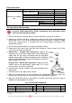
12. Operate the pool heater, test for gas leaks using soapy water solution and adjust the
burner pressure to that indicated on the rating label (refer to „Burner Pressure
Adjustment‟ procedure on page 41).
13. Complete reassembly.
Refractories & Top Refractory Retainers
Risk of skin and respiratory irritation. Gloves, face mask and overalls must
be worn when handling the refractories. Spent refractories should be sealed
in a plastic bag for disposal.
1. Isolate the gas supply to the pool heater.
2. Follow steps 1-11 of the „In/Out Header‟ procedure on page 49.
3. Follow steps 3 & 4 of the „Heat Exchanger‟ procedure on page 50.
4. Remove the Igniter & Flame Rod Assembly. Refer to „Igniter & Flame Rod Assembly‟
on page 54.
5. Lift out the front and rear top refractory retainers.
6. Lift out the left refractory. Note: Refractories are tight fitting and need to be worked out
gradually. Pay attention to how the Refractories are assembled as the front and side
Refractories are not interchangeable.
7. Lift out right Refractory.
8. Lift out front and rear Refractories.
9. Reassemble in reverse order of above. Note: Ensure the Heat Exchanger ends are
aligned with the edges of the left and right hand Refractories when reinstalling. Ensure
the water connection union o-rings are clean before reassembly and use silicone
grease on o-rings if required.
10. Restore the pool water supply, start the pool pump and check for water leaks.