
Operating instructions


41
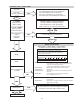
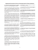
Igniter
.18” ± .03”
.26” MIN ALONG
LENGTH OF RODS
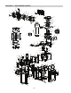
ORIFICE REMOVAL
1. Locate and close the external manual shut-off
valve.
2. Loosen the external gas union.
3. Locate and remove front door panel.
4. Locate and remove the (4) bolts & nuts holding the
gas orifice in place. See the figure above.
5. Carefully remove the gas orifice and do not mis-
place the o-rings attached to the flanges.
6. Inspect and/or replace the orifice with the correct
size.
IGNITER REMOVAL
1. Locate and remove front door panel.
2. Locate and remove the accessible left or right side
access panel. If neither is accessible, you may
either reach from the front of the heater or remove
the jacket top for better access. See “Jacket Top
Removal” for instructions.
3. Locate the igniter behind the blower.
4. Locate and disconnect the high tension spark
cable from the igniter.
5. Using a 5/16” socket, remove the (2) bolts holding
the igniter down.
6. Using a flat screw driver, loosen the igniter brack-
et from the combustion chamber, preferably on
both sides.
7. Carefully remove the igniter from its location. The
ceramic is fragile, so handle with care.
8. When replacing or inspecting the igniter, the gap
between the ground & spark tips should be 0.18”±
0.03”. The gap between the rods should be no
less than .23” along their entire length.
BRACKET
O-RING
G
AS ORIFICE
Be sure that electrical service to the heater has prop-
er overload fuse or circuit breaker protection, wire size
and connections which comply with all applicable
codes.
VISUAL INSPECTION
E
LECTRICAL
Flames can be observed through the sight glass
reflection below the blower motor. A blue colored
flame indicates normal operation. At least every three
months a visual inspection should be made.
CAUTION: Prior to replacing any component,
make sure that the main gas, power, and pumps
are turned OFF.
AIR ORIFICE
GAS ORIFICE
M
UST MATCH
F
OR CORRECT
AIR/FUEL RATIO
4
POCKETS
4
NOTCHES
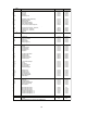
Pockets / Notches Model Elevation
1 409 0-2000 ft
2 259 0-2000 ft
3 409 2000-5000 ft
4 259 2000-5000 ft
5 409 5000-7000 ft
6 259 5000-7000 ft
GAS AND AIR ORIFICE SELECTION
The gas orifice and the air orifice MUST match to
attain the correct air/fuel ratio. The orifices are
matched when the number of pockets on the side of
the gas orifice is the same as the number of notches
on the edge of the air orifice.
The gas orifice is located on the gas train, between the
gas valve and the combustion blower. The air orifice
is located on the inlet side of the combustion blower.
NOTE: Orifices for propane gas have a black oxide
finish.