
INSTALLATION AND OPERATING INSTRUCTIONS Advanced Design Boiler 751, 1001, 1501

23
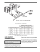
Gas Pressure Regulator
The gas pressure regulator is nominally preset to the
outlet values shown in Tables T and U, within +.1 in.
WC. If an adjustment is needed, turn the adjustment
screw clockwise to increase pressure or counterclock-
wise to lower pressure.
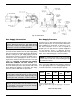
Venting of Diaphragm Gas
Components
Boilers have gas train components that have
diaphragms in their construction that are supplied with
a bleed line connection that must be connected to the
outside atmosphere as required by NFGC or (for
Canada) the B149 Installation code and applicable
provisions of local codes. Under NO circumstances
shall bleed lines terminate in the gas utilization equip-
ment flue or exhaust system.
ELECTRICAL POWER
CONNECTIONS
Installations must follow these codes:
· National Electrical Code and any other national,
state, provincial or local codes or regulations having
jurisdiction.
· Safety wiring must be N.E.C. Class 1.
· Boiler must be electrically grounded as required by
N.E.C. ANSI/NFPA 70-latest edition.
· In Canada, C.S.A. C22. 1 C.E.C. Part 1.
The boiler is wired for 120 VAC. The voltage is indicat-
ed on the tie-in leads. Consult the wiring diagram
shipped with the boiler in the instruction packet. The
“TH” leads are connected to the remote tank control
stat, thermostat, or electronic boiler control as applica-
ble. 24 Volts are supplied to this connection through
the boiler transformer. DO NOT attach line voltage to
the “TH” leads. Before starting the boiler check to
insure proper voltage to the boiler and pump.
Install a separate disconnect means for each load.
Use appropriate-sized wire as defined by NEC, CSA
and/or local code. All primary wiring should be 125% of
minimum rating.
It is strongly recommended that all individually-pow-
ered control modules and the boiler should be
supplied from the same power source.
Surge Protection
Microprocessor-based and solid state controls are vul-
nerable to damage from voltage and amperage
fluctuations in the power supply. All sensitive control
components should be protected by a suitable com-
mercial-grade surge protection device.
If any of the original wire as supplied with the boiler
must be replaced, it must be replaced with 105°C wire
or its equivalent.
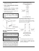
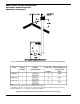
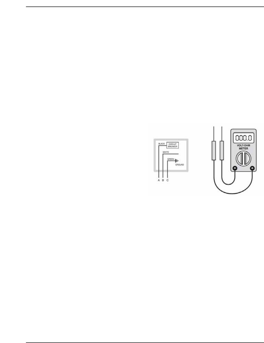
Check the Power Source
Using a volt-ohm meter (VOM), check the following
voltages at the circuit breaker panel prior to connect-
ing any equipment: Make sure proper polarity is
followed and house ground is proven.
AC = 108 Volts AC Minimum, 132 Volts MAX
AB = 108 Volts AC Minimum, 132 Volts MAX
BC = Must be less than 1.0 Volts AC
Making the Electrical Connections
Refer to Fig. 18 and the wiring diagram.
1. Verify circuit breaker is properly sized by referring
to boiler rating plate. A dedicated motor duty circuit
breaker should be provided.
2. Turn off all power to the boiler. Verify that power
has been turned off by testing with a volt-ohm
meter prior to working with any electrical connec-
tions or components.
3. Observe proper wire colors while making electrical
connections. Many electronic controls are polarity
sensitive. Components damaged by improper
electrical installation are not covered by warranty.
Fig. 17: Check Power Source