INSTALLATION & OPERATING INSTRUCTIONS Raytherm™ Residential Boilers Models 0042B, 0066B, 0090B 0135B & 0180B – Type H WARNING: If these instructions are not followed exactly, a fire or explosion may result causing property damage, personal injury or death. FOR YOUR SAFETY: Do not store or use gasoline or other flammable vapors and liquids or other combustible materials in the vicinity of this or any other appliance. To do so may result in an explosion or fire.
Rev.
CONTENTS WARNINGS Pay Attention to These Terms RECEIVING EQUIPMENT GENERAL SPECIFICATIONS INSTALLATION Code Requirements Mounting Base Clearance Requirements Combustion/Ventilation Air Venting Connections Vent Damper Installation Location VENT DAMPER WIRING DIAGRAM Gas Supply Connections Gas Pressure Water Connections & System Piping Electrical Wiring WIRING DIAGRAMS SERVICING PROCEDURES General Location of Controls SEQUENCE OF OPERATION Intermittent Ignition Device (IID) START-UP PROCEDURES Lighting the Bo
WARNINGS Pay Attention to These Terms DANGER: WARNING: CAUTION: NOTE: Indicates the presence of immediate hazards which will cause severe personal injury, death or substantial property damage if ignored. Indicates the presence of hazards or unsafe practices which could cause severe personal injury, death or substantial property damage if ignored. Indicates the presence of hazards or unsafe practices which could cause minor personal injury or product or property damage if ignored.
RECEIVING EQUIPMENT GENERAL SPECIFICATIONS On receipt of your equipment, visually check for external damage to the carton. If the carton is damaged, it is suggested that a note be made on the Bill of Lading when signing for the equipment. Raytherm hydronic boilers are design certified and tested under the requirements of the latest edition of the American National Standard, ANSI Z21.13/CSA 4.9.
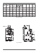
Model No. Input MBH Heating Capacity MBH Net I=B=R Rating H-0042 42 35 30 H-0090 90 74 64 H-0066 66 H-0135 54 135 H-0180 47 109 180 95 148 129 Piping Connections Water NPT Gas NPT 1 in. 1/2 in. A B C K Vent Dia. 1 in. 1/2 in. 11 in. 5 3/4 in. 5 1/2 in. 4 in. 1 in. 1/2 in. 11 in. 5 3/4 in. 5 3/4 in. 5 in. 1 1/4 in. 11 in. 1/2 in. 1 1/4 in. 18 in. 1/2 in. 18 in. 5 3/4 in. 5 3/4 in. 6 1/4 in. 5 in. 6 1/4 in. 6 1/4 in. 6 in. 8 in. 7 in.
INSTALLATION Code Requirements Installation must be in accordance with local codes, or in the absence of local codes, with the latest editions of the National Fuel Gas Code, ANSI Z223.1, and the National Electrical Code, ANSI/NFPA 70. In Canada, installations must conform with the current CSA B149 and the Canadian Electrical Code Part 1 CSA C22.2 No.1.
3. Except for carpeted flooring, boilers are certified for installation on combustible floors. One opening shall be within 12" of the top, and the other opening within 12" of the floor. If additional gas appliances are installed in the same space, the total input of all gas appliances installed in the same space, must be considered in the calculation. Refer to the latest edition of the National Fuel Gas Code for additional requirements. 4.
Location of the openings is the same as in the previous case - that is, within 12" of the top, and within 12" of the bottom of the enclosure. If horizontal ducts are used, the area must be doubled and the duct area shall not be less than the area of the openings they connect, and in no case shall the smallest dimension be less than 3". The discharge opening must be a minimum of two (2) feet vertically from the roof surface and at least two (2) feet higher than any part of the building within ten (10) feet.
Roof Pitch (X/12) H (Min. ft) 6/12 to 7/12 1.25 Over 8/12 to 9/12 2 Flat to 6/12 Over 7/12 to 8/12 Over 9/12 to 10/12 1 1.5 3.25 Over 12/12 to 14/12 5 Over 14/12 to 16/12 Over 16/12 to 18/12 Over 18/12 to 20/12 Over 20/12 to 21/12 Refer to Fig. 4 for graphical reference For connections to gas vents or chimneys, vent installations shall be in accordance with the Venting of Equipment section of the National Fuel Gas Code, ANSI Z223.1, or applicable provisions of the local building codes. 2.
Vent Damper Installation Location At the time of removal of an existing boiler, the following steps shall be followed with each appliance remaining connected to the common venting system placed in operation, while the other appliances remaining connected to the common venting system are not in operation. The vent damper supplied with each boiler must be located in the vent so that it serves only the appliance for which it is intended. 1. Seal any unused openings in the common venting system.
Mounting On vertical vents, the vent damper may be mounted with the actuator in any position. On horizontal vents, do not mount the actuator either directly above or directly below the vent pipe; mount the vent damper actuator to the side of the vent. The vent damper is set up for a continuous pilot system.
NOTE: To place vent damper in the open position to allow burner operation: Turn the power off. Turn the damper blade to fully open position (arrow facing same direction as vent pipe). Turn power on. 24 2. Turn the thermostat or controller up to call for heat and check that the vent damper indicator points to the open position, as shown in Fig. 11.
VENT DAMPER 14
Model 1/2 in. Pipe No. Nat. Pro. 0042 125 350 0090 30 80 0066 0135 0180 60 15 160 40 20 3/4 in. Pipe Nat. Pro. 175 460 60 150 500 125 35 1 in. Pipe Nat. Pro. 300 400 90 115 200 450 300 1 1/4 in. Pipe Nat. Pro. 425 Table H: Maximum Equivalent Pipe Length (Feet) Gas Supply Connections NOTE: Do not use teflon tape on gas line pipe thread. A flexible sealant suitable for use with Natural and Propane gases is recommended. The inlet gas connection of the boiler gas valve is 1/2".
shipped loose. The full open position is appropriate for most systems, and ensures adequate flow through the boiler. Systems with multiple zones may require an additional circulator. Consult manufacturer's data for valve pressure drops. When an indirect water heating system is used, it is recommended that a separate circulator be installed to meet the required flow and pressure drop conditions of the indirect water heater.
Piping Diagrams Air Vent Air Scoop Feed Valve Diaphragm Expansion Tank Pipe Pressure Relief Valve to Drain Cold Water Inlet Heating Units Fig. 15: Single-Zone Piping 12” Max. Air Vent Air Scoop Feed Valve Circulators Diaphragm Expansion Tank Pipe Pressure Relief Valve to Drain Cold Water Inlet Heating Units Fig.
Electrical Wiring The room thermostat should be installed in accordance with the manufacturer's instructions. The thermostat heat anticipator should be set at 1.0 ampere (automatic ignition) and 0.60 ampere (standing pilot) for single- zone installations. For multi-zone applications, the heat anticipator setting should be based on the ampere load in the thermostat circuit. The electrical power supply requirement for these boilers is 120 VAC, 60 Hz.
Wiring Diagrams 19
Fig. 17: Single-Zone Taco Valve NOTE: Maximum three (3) zone valves per one (1) 40 VA transformer. Fig. 18: Dual-Zone Taco Valve NOTE: Maximum five (5) zone valves per one (1) 40 VA Transformer. Fig.
NOTE: Check VA rating of each relay coil. Total load must not exceed VA rating of transformer. Fig. 20: System with Three (3) Zone Pumps Fig.
Fig. 22: Primary/Secondary Pumping System Honeywell Zone Valve Note: Low water cut-off (LWCO) and system switch supplied by others. Fig.
Note: Low water cut-off (LWCO) and system switch supplied by others. Fig.
SERVICING PROCEDURES SEQUENCE OF OPERATION General Location of Controls Intermittent Ignition Device (IID) Boilers equipped with the IID system will automatically light the pilot burner first and then the main burner, each time there is a call for heat from the room thermostat. Whenever the room thermostat is calling for heat, the circulator supplied with the boiler will be energized and should be running.
START-UP PROCEDURES Filling the System Flush system before putting into operation to ensure that foreign material does not damage pump seals. Fill system with water. Purge all air from the system using purge valve sequence. After system is purged of air, lower system pressure. Open valves for normal system operation, fill system through feed pressure regulator to minimum 12 psi. Manually open air vent on the compression tank until water appears, then close vent.
For Standing Pilot Models with Robertshaw Gas Valve, 2-stage Operation (Models 90, 135 & 180) 1. 2. 3. 4. *If lever does not spring back to "PILOT" position when released, stop and immediately call your service technician or gas supplier. *If the pilot does not stay lit after several tries, move the gas control lever to "OFF" and call your service technician or gas supplier. 9. Stand to the side of the boiler and move the gas control lever counter-clockwise to "ON". 10.
technician. Force or attempted repair may result in a fire or explosion. GAS CONTROL KNOB SHOWN IN "OFF" POSITION D. Do not use this boiler if any part has been under water. Immediately call a qualified service technician to inspect the boiler and to replace any part of the control system and any gas control which has been under water. GAS INLET For Intermittent Ignition (IID) with Honeywell or Robertshaw Gas Valve (All Models) 1. 2. 3. 4. ROBERTSHAW (All Models) Fig.
3. Turn off all gas valves supplying gas to the boiler. Refer to operating instruction label on the boiler. 4. Shut-off the water supply to the boiler piping system loop. 5. Open drain valve on the boiler to remove water from the boiler and the piping circuits. e. Replace pilot adjustment cover screw, then follow the lighting instructions to get boiler ready for operation.
Inspection Procedures *3. *4. *5. *6. Inspect pilot and main burner flame and firing rate. Inspect and operate all controls and gas valve. Visually inspect system for water leaks. Inspect oil pump motor and bearing assembly, if oil cups are provided. 7. Check flow switch paddle. 8. Clean room air intake openings to ensure adequate flow of combustion and ventilation air. 9. Keep boiler area clear and free from combustible materials, gasoline, and other flammable vapors and liquids.
REPAIR PROCEDURES Burner Tray Removal 1. Shut-off power and gas supply to the boiler. Disconnect union(s) and pilot tubing when present; then loosen and remove burner hold-down screws. 2. Disconnect wires at gas valve and slide burner tray out. Tube Cleaning Procedure (Typical) Establish a regular inspection schedule, the frequency of which depends on the local water condition and severity of service. Do not let the tubes clog up solidly. Clean out deposits over 1/16" in thickness.
Heat Exchanger Re-assembly 9. Install flue collector, jacket top and inspection panels. Install top holding screws. Install draft diverter and vent piping if so equipped. 1. Heat exchanger water header O-rings should be replaced with new ones. 10. If gas piping was disconnected, reconnect gas piping system and check for leakage using a soap solution. 2. Install in/out and return water headers and install header retainer nuts and torque nuts evenly. 11.
TROUBLESHOOTING These instructions are primarily intended for the use of qualified personnel specifically trained and experienced in the installation of this type of heating equipment and related system components. Installation and service personnel may be required by some states to be licensed. Persons not qualified shall not attempt to install this equipment nor attempt repairs according to these instructions. PROBLEM 1)When room thermostat is turned on, boiler does not operate.
3) Pilot Outage. (Standing pilot models) 4) Yellow lazy flame. 10) Defective ignition module or defective gas valve. 10) Before module goes into a lock-out, check voltage across MV and MV/ PV. If no 24V is present, replace module. If 24V is present, replace gas valve. 1) Too low or too high gas pressures. 2) Restricted pilot. 3) Weak thermocouple. 1) Adjust inlet gas pressure as shown on rating plate. 2) Clean pilot orifice. 3) Replace thermocouple. 1) Too low gas pressure.
Adjustment & Replacement of Components Flame Roll-out Switch Replacement DANGER—SHOCK HAZARD: Make sure electrical power to the boiler is disconnected to avoid potential serious injury or damage to components. 1. Shut-off electrical power and gas supply to the boiler. 2. Remove gas piping to gas valve inlet. 3. Disconnect wiring connections, pilot tubing (when present). 4. Remove screws (2) holding the burner tray. 5. Slide burner tray out. 6. Remove gas valve bracket screws and bracket. 7.
2-Stage Controller (Models 90, 135 & 180) 7. Remove the wedge or retaining clip holding the sensing bulb in the control well in the in/out header. 8. Pull out the sensing bulb carefully from the control well. 9. Remove the limit control with capillary from unit. 10. Reverse above procedure to re-install. 1. Shut-off electrical power to the boiler. 2. Remove control cover screws and open control compartment. 3. The control is factory set at 160°F.
LIMITED PARTS WARRANTY RESIDENTIAL HEATING BOILERS MODELS 42 TO 180 Catalog No.: 1910.10H Effective: 01-01-04 Replaces: 05-15-03 SCOPE: Raypak, Inc. (“Raypak”) warrants to the original owner that all parts of this boiler which are actually manufactured by Raypak will be free from failure under normal use and service for the specified warranty periods and subject to the conditions set forth in this Warranty.
www.raypak.com Raypak, Inc., 2151 Eastman Avenue, Oxnard, CA 93030 (805) 278-5300 Fax (805) 278-5468 Litho in U.S.A.