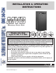
INSTALLATION & OPERATING INSTRUCTIONS Models 504–2004 Types H, WH, P & WHP L W WARNING: Improper installation, adjustment, alteration, service or maintenance can cause property damage, personal injury, exposure to hazardous materials* or loss of life. Review the information in this manual carefully. *This unit contains materials that have been identified as carcinogenic, or possibly carcinogenic, to humans.
Rev. 4 reflects the following: Changes to: Table J on page 20; Fig. 16 on page 21; the Heater Sequence of Operation section on page 36; the UDB Diagnostic Board section on page 39; the Wiring Diagrams on pages 40 and 41; Table V and Table X on page 44; and the UDB Fault History section on page 49. The addition of: A wiring diagram note at the bottom of page 39. California Hot Water Supply, Inc.
CONTENTS WARNINGS BEFORE INSTALLATION Product Receipt Model Identification Ratings and Certifications Installations at Elevation Component Locations General Information GENERAL SAFETY Time/Temperature Relationships in Scalds INSTALLATION Installation Codes Equipment Base Clearances Combustion and Ventilation Air Conventional Combustion Air Supply Water Piping Hydronic Heating Gas Supply Electrical Power Connections Field Wiring Connection Venting Venting Installation Tips 4 5 5 5 5 5 6 6 7 Venting Configu
WARNINGS Pay Attention to These Terms DANGER: Indicates the presence of immediate hazards which will cause severe personal injury, death or substantial property damage if ignored. WARNING: Indicates the presence of hazards or unsafe practices which could cause severe personal injury, death or substantial property damage if ignored. CAUTION: Indicates the presence of hazards or unsafe practices which could cause minor personal injury or product or property damage if ignored.
BEFORE INSTALLATION Raypak strongly recommends that this manual be reviewed thoroughly before installing your MVB heater. Please review the General Safety information before installing the heater. Factory warranty does not apply to heaters that have been improperly installed or operated. (Refer to the warranty at the back of this manual.) Installation and service must be performed by a qualified installer, service agency or gas supplier.
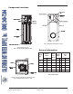
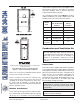
Component Locations Fig. 3: Component Locations – Rear Panels omitted for clarity Fig. 1: Component Locations – Side General Information MBTUH Input* Model No. Water Conn. (NPT) Max.* Min.* Gas Conn. (NPT) N P Vent Size (in.) Flue Intake 504 500 350 2 1 1 8 6 754 750 525 2 1 1 10 6 1104 1100 770 2-1/2 1-1/4 1 10 6 1504 1500 1050 2-1/2 1-1/4 1 12 8 2004 1999 1400 2-1/2 2 1 14 8 *H7 units only.
GENERAL SAFETY To meet commercial hot water use needs, the high limit safety control on this water heater will shut off the main gas valve before the outlet temperature reaches 210°F. However, water temperatures over 125°F can cause instant severe burns or death from scalds. When supplying general purpose hot water, the recommended initial setting for the temperature control is 125°F. This section applies to Hot Water Supply Boilers and Hot Water Heaters ONLY.
Equipment Base The temperature of the water in the heater can be regulated by using the Raypak Modulating Temperature Control. To comply with safety regulations, the control is set at 120°F when shipped from the factory (Mode 3 default setting for Tank Target). The heater should be mounted on a level, structurally sound surface. The heater is approved for installation on a combustible surface but must NEVER be installed on carpeting.
codes and the requirments of the gas supplier. Three sides must be open in the area under the overhang. Roof water drainage must be diverted away from heaters installed under overhangs. The combustion air intake terminal MUST be used for outdoor installations. The hood is shipped loose and installed on the rear of the heater at the job site. Heater Side Min.
Fig. 6: Minimum Clearances from Vent/Air Inlet Terminations – Indoor and Outdoor Installations 1 1 2 t TT * 2 U.S. Installations Canadian Installations A Clearance above grade, veranda, porch, deck, or balcony 1 ft (30 cm) 1 ft (30 cm) B Clearance to window or door that may be opened 4 ft (1.
Optional Construction Air Filter An optional construction air filter is available for use. The filter should be removed after construction is finished to allow for unrestricted air flow to the heater. Conventional Combustion Air Supply Direct Vent If outside air is drawn through the intake pipe directly to the unit for combustion: 1. Install combustion air direct vent in accordance with Fig. 24 (horizontal) or Fig. 25 (vertical) of this manual (pages 28 and 29, respectively). 2.
b. Where communicating with the outdoors through horizontal ducts, each opening shall have a minimum free area of 1 in.2 per 2,000 BTUH (1,100 mm2 per kW) of total input rating of all equipment in the enclosure. and terminated 18 in. (450 mm) from the floor, but not near piping. This air supply opening requirement shall be in addition to the air opening for ventilation air required in 1. (above). WARNING: Care must be taken to ensure that the equipment room is not under negative pressure conditions. 2.
Relief Valve Piping This heater is equipped with a proprietary condensate evaporation system which will evaporate any condensate that may begin to accumulate inside the primary heat exchanger with water temperatures as low as 120°F (49°C). WARNING: Pressure relief valve discharge piping must be piped near the floor and close to a drain to eliminate the potential of severe burns. Do not pipe to any area where freezing could occur. Refer to local codes.
longer needed and the bypass can be shut off. If the bypass is not shut off as the system heats up, the outlet temperature may continue to climb and trip the high limit, thereby shutting down the heater. Thus an automatic valve system, such as a three-way proportional valve or a modulating two-way valve to control the bypass, should be utilized. * *Maximum 4 times the pipe diameter or 12”, whichever is less. Fig.
Model No. Input Output MBTUH 20° ΔT 30° ΔT gpm ΔP gpm ΔP 40° ΔT gpm Min. Flow ΔP Max. Flow gpm ΔP ΔT gpm ΔP ΔT 25 1.1 34 100 11.3 8 504 500 420 42 2.7 28 1.4 754 750 630 63 6.0 42 2.9 32 1.7 32 1.7 40 100 13.8 13 1104 1100 924 92 13.3 62 6.7 46 4.1 46 4.1 40 113 18.6 16 1504 1500 1260 84 13.3 63 8.0 63 8.0 40 113 22.2 22 2004 1999 1679 112 26.9 84 16.0 84 16.0 40 113 27.2 30 Note: Basis for minimum flow is ΔT.
Domestic Hot Water Potable Water and Space Heating When designing the water piping system for domestic hot water applications, water hardness should be considered. Table G indicates the suggested flow rates for soft, medium and hard water. Water hardness is expressed in grains per gallon. CAUTION: When this heater is used for both potable water and space heating, observe the following to ensure proper operation. 1.
increase the inlet water temperature to a minimum of 105°F (40°C) for Pool Heater (P and WHP) versions and 120°F (49°C) for Hydronic Heating (H7) or Domestic Hot Water (WH1) versions, thereby reducing the likelihood of condensation forming on the heat exchanger. The pump also serves to circulate water through the heater from the main system piping. 2. Turn on heater and wait until heater goes to full fire. 3.
NOTE: There are 2 separate drains on the MVB that must BOTH be drained to protect the heat exchanger. These are both accessible by removing the lower front door from the heater. Drain any piping of all water that may experience belowfreezing temperatures. Pool/Spa Water Chemistry CAUTION: Corrosive water voids all warranties. NOTE: Chemical imbalance can cause severe damage to your heater and associated equipment. Chemical imbalance can cause severe damage to the pool heater and associated equipment.
Further advice should be obtained from your pool or spa builder, accredited pool shop, or chemical supplier for the correct levels for your water. Automatic Chlorinators and Chemical Feeders All chemicals must be introduced and completely diluted into the pool or spa water before being circulated through the heater. Do not place sanitizing chemicals in the skimmer. High chemical concentrations will result when the pump is not running (e.g. overnight).
Model No. 1 in. NPT 1-1/4 in. NPT 1-1/2 in. NPT 2 in. NPT N P N P N P 504 15 35 65 150 150 360 754 5 15 35 75 70 175 250 1104 15 35 35 75 1504 10 20 20 45 2004 N 2-1/2 in. NPT P N P 100 250 225 60 150 150 275 35 85 85 200 Natural Gas – 1,000 BTU/ft3, 0.60 specific gravity at 0.5 in. WC pressure drop Propane Gas – 2,500 BTU/ft3, 1.53 specific gravity at 0.6 in.
WARNING: Using a multi-meter, check the following voltages at the terminal block inside the unit. Make sure proper polarity is followed and house ground is proven. (See Fig. 17.) Check the power source: AC = 108 VAC Minimum, 132 VAC MAX AB = 108 VAC Minimum, 132 VAC MAX BC = <1 VAC Maximum Fig. 16: Wiring Electrical Connections Field-Connected Controllers Fig.
temperature that avoids excessive condensate production in the vent. NOTE: A grounding electrode conductor shall be used to connect the equipment grounding conductors, the equipment enclosures, and the grounded service conductor to the grounding electrode. Category II – A heater which operates with a non-positive vent static pressure and with a vent gas temperature that may cause excessive condensate production in the vent.
Combustion Air Supply From Inside Building (Non-Direct Venting) From Outside Building (Direct Venting) Exhaust Configuration Heater Venting Category Certified Materials Vertical Venting I B-Vent Equivalent Horizontal Throughthe-Wall Venting III Stainless Steel AL29-4C Vertical Venting I B-Vent Equivalent Horizontal Throughthe-Wall Venting III Stainless Steel AL29-4C Combustion Air Inlet Material Galvanized Steel PVC ABS CPVC Table K: Venting Category Requirements 1.
7. The vent terminal requires a 12 in. vent terminal clearance from the wall. 8. Terminate vent at least 1 ft above grade, including normal snow line. 9. Multiple direct vent installations require a 4 ft clearance between the ends of vent caps located on the same horizontal plane. Venting Installation Tips Support piping: • • • horizontal runs—at least every 5 ft vertical runs—use braces under or near elbows WARNING: Examine the venting system at least once a year.
Model No. Certified Vent Material Vent Size (in.) Min. 504 8 754 10 1104 Category I (Type B Equivalent) 1504 Vertical Vent Height1 (ft) 10 Max. 5 25 12 Combustion Air Intake Pipe Material Galvanized Steel, PVC, ABS, CPVC Air Inlet Max. Length* (ft) 6” Ø 8” Ø 45 100** 45 2004 10” Ø 85** 14 1 Vent lengths are based on a lateral length of 2 ft. Refer to the latest edition of the NFGC for further details. When vertical height exceeds 25 ft, consult factory prior to installation.
CAUTION: A listed vent cap terminal adequately sized, must be used to evacuate the flue products from the heaters. Common Venting Manifolds that connect more than one heater to a common chimney must be sized to handle the combined load. Consult available guides for proper sizing of the manifold and the chimney. At no time should the area of the common vent be less than the area of the largest heater exhaust outlet.
system. Turn on any exhaust fans, such as range hoods and bathroom exhausts, at maximum speed. Do not operate summer exhaust fan. Close fireplace dampers. 4. Place in operation the appliances being inspected. Follow the manufacturer’s instructions for lighting each appliance. Adjust thermostat so appliance will operate continuously. 5. Check the pressure at a pressure tap located 12 in. above the bottom joint of the first vertical vent pipe. Pressure should be anywhere between -0.01 and -0.08 in. WC. 6.
• • • • NOTE: While a drain connection is required in the vent of all Cat. III horizontal MVB installations, the drain can be accomplished in several different ways. The figures in this manual show the drain in a vent tee, however, this can also be accomplished using an inline collector for condensing stacks or an inline vertical or horizontal collector available from several of the listed vent manufacturers.
Certified Vent Material Model No. Vent Size (in.) Min. 504 8 754 10 Category III 1104 1504 Horizontal Vent Height1 (ft)* 10 Max. 0 75 12 Combustion Air Intake Pipe Material Galvanized Steel, PVC, ABS, CPVC Air Inlet Max. Length** (ft) 6” Ø 8” Ø 45 100t 45 2004 10” Ø 85t 14 * Vent lengths are based on a lateral length of 2 ft. Refer to the latest edition of the NFGC for further details. ** Subtract 10 ft per elbow. Max. 4 elbows. t Adapters supplied by others.
2. 3. Freeze Protection Periodically check venting system. The heater’s venting areas must never be obstructed in any way and minimum clearances must be observed to prevent restriction of combustion and ventilation air. Keep area clear and free of combustible and flammable materials. The Raypak electronic temperature control includes a freeze protection feature.
maintain near 160ºF system supply temperature, and if the system ΔT is 10ºF, then the system return (target) set-point is 160-10=150ºF. Deadband: Deadband is a band of temperature sensing where no action occurs. All temperature controllers have a deadband and the purpose is to prevent shortcycling of the heater. The on-board temperature controller has a deadband of 2ºF around the differential. Differential: A heat source must be operated with a temperature differential in order to prevent shortcycling.
water is also controlled to the boiler target temperature (factory default WH1 water heaters). See Fig. 30. Mode 7 – Designed for an external input signal with primary/secondary piping. The external input signal can be provided from a BMS, an EMS or a sequencing control. The external input signal changes the boiler target according to a linear scale (see Tables O & P). The control operates the boiler burner to maintain the boiler target at the remote system sensor. See Fig. 32. ELECTRONIC Fig.
2-10 VDC 4-20 mA* Boiler Target 0 0 --- (OFF) 1 2 --- (OFF) 2 4 50°F 3 6 71.3°F 4 8 92.5°F 5 10 113.8°F 6 12 135°F 7 14 156.3°F 8 16 177.5°F 9 18 198.8°F 10 20 220°F BOIL SUP - Actual system supply water temperature. BOIL TARGET - Target temperature that the heater is trying to maintain. ‘BURNER’ DELAY - Holds control output at ignition setting from the start of the ignition sequence to the specified burner delay time (0 to 3:00 min.).
Boiler (H7) Item Modes Default Setting Range 2 140°F OFF, 70 to 220°F 3 160°F OFF, 70 to 190°F 5, 7 180°F OFF, 70 to 220°F 2, 5, 7, 8 200°F OFF, 120 to 225°F 3 180°F OFF, 120 to 190°F Boil Min 2, 3, 5, 7 135°F OFF, 80 to 180°F ‘Burner’ Delay All 0:00 min 0:00 to 3:00 min Boil Mass All 1 (Low) 1 (Low), 2 (Med), 3 (High) Diff 2, 3, 5, 7 Auto Auto, 2 to 42°F DHW Target 3 120°F OFF, 70 to 190°F DHW Diff 3 5°F 2 to 10°F ‘Pump’ Dly All 3:00 min OFF, 0:20 to 9:55 min,
Water Heater (WH1) Item Modes Default Setting Range 2 140°F OFF, 70 to 190°F 3, 7 160°F OFF, 70 to 190°F Boil Max 2, 3, 6, 7 180°F OFF, 120 to 190°F Boil Min 2, 3, 7 135°F OFF, 80 to 180°F ‘Burner’ Delay All 0:00 min 0:00 to 3:00 min Boil Mass All 1 (Low) 1 (Low), 2 (Med), 3 (High) Diff 2, 3, 7 Auto Auto, 2 to 42°F DHW Target 3 120°F OFF, 70 to 190°F DHW Diff 3 5°F 2 to 10°F ‘Pump’ Dly All 3:00 min OFF, 0:20 to 9:55 min, ON Units All °F °F or °C Mode N/A 3 2,
Rank Item Field Number Field Type Fault Description 0 E01 Err Error EEPROM error 1 FP Err Warning Flame proof warning 2 BOIL OUT SHr Error Boiler outlet sensor short 3 BOIL OUT OPn Error Boiler outlet sensor open 4 BOIL IN SHr Error Boiler inlet sensor short 5 BOIL IN OPn Error Boiler inlet sensor open 6 SUP SHr Error System sensor short 7 SUP OPn Error System sensor open 8 OUTDR SHr Error Outdoor sensor short 9 OUTDR OPn Error Outdoor sensor open 10 D
Ignition Module High Limit—Manual Reset When additional heat is needed, the combustion air blower starts to purge air from the combustion chamber for 15 seconds. On proof-of-air flow, the air-proving switch closes and the igniter is energized. To ensure safe operation, the gas valve cannot open until the igniter is verified. The main burner is automatically lit when the device is powered and pre-purged.
High Limit—Auto Reset (Optional) Modulating Temperature Control This heater may be equipped with an optional adjustable auto reset high limit temperature device. This heater is equipped with a Raypak modulating temperature control. Refer to information starting on page 31 for information on the setting and use of this control. The optional adjustable auto reset high limit is located inside the heater junction box. Adjust the setting to approx. 20°F (10°C) above desired outlet temperature. Fig.
er valve/regulator performance. The low gas pressure switch automatically shuts down the heater if gas supply drops below the factory setting of 3.0 in. WC for natural gas or propane gas. The optional high gas pressure switch connection mounts down-stream of the gas valve.
WIRING DIAGRAM - California Hot Water Supply, Inc.
WIRING DIAGRAM - Models P & WHP California Hot Water Supply, Inc.
START-UP WHAT TO DO IF YOU SMELL GAS: • • Pre Start-up • Filling System (Heating Boilers) Fill system with water. Purge all air from the system. Lower system pressure. Open valves for normal system operation, and fill system through feed pressure. Manually open air vent on the compression tank until water appears, then close vent. Air Purge (Domestic Hot Water Heaters) • • • Purge all air from system before lighting heater. This can be normally accomplished by opening a downstream valve.
Check Power Supply With multi-meter at incoming power, check voltage between: Hot - Common (≈120 VAC) 3. If the gas pressure is greater than 14.0 in. WC, turn off the main gas shut-off valve. Start-Up NOTE: The values in Tables V, W and X represent the conditions when the heater is at full firing rate at sea level. Hot - Ground (≈120 VAC) Common - Ground (< 1 VAC) 1. Turn power on. 2.
pressure should read per the values in Table X for natural and propane gas. 2. If the pressure reading differs by more than ± 0.2 in. WC, STOP – Call the factory for directions on what to do next! Model No. 504 754 1104 1504 2004 Air Pressure Setting (in. WC) -2.3 -2.9 -4.0 -4.0 -4.1 Setting Tolerance ± 0.2 in. WC ± 0.2 in. WC ± 0.2 in. WC ± 0.2 in. WC ± 0.2 in. WC Table V: MVB Air Pressure Settings Model No. Amp Draw 504 754 1104 1504 2004 1.9 2.9 5.5 8.1 13.0 Setting Tolerance +0.0/-0.2 +0.0/-0.
Leak Test Procedure: Dual-Seat Gas Valve 7. After no leakage has been verified at all valve seats and test valves, open downstream leak test valve and restore electrical power to the heater. Proper leak testing requires three pressure test points in the gas train. Remove the access panel on the rear of the heater to access the gas valve for this test. Test point A is a bleedle valve located upstream of the combination gas valve on the supply manifold.
8. 9. for operation as outlined by manufacturer. Burner should be operating and should go off when controls are tested. When safety devices are restored, burners should re-ignite after pre-purge time delay. OPERATION Test limit control: While burner is operating, move indicator on high limit control below actual water temperature. Burner should go off while blower and circulator continue to operate.
d. Gas is on at the meter and the heater. e. Incoming dynamic gas pressure to the gas valve is NOT less than 4.0 in. WC for natural gas or propane gas. To Turn Off Gas To Appliance 1. Shut off manual gas valve field installed near gas inlet connection on back of heater. 2. Remove upper front panel. 3. Set the thermostat to lowest setting. 4. Turn off all electrical power to the appliance if service is to be performed. 5. Replace access panel. California Hot Water Supply, Inc.
TROUBLESHOOTING Step 1 Does the power switch provide power to the control panel? Check the switch and/or line voltage NO Is there a Call For Heat? YES NO Unit is in standby mode. YES Step 2 NO Is Disable connection intact? Reattach. YES Step 3 Does the combustion air blower come on? Is there 120VAC at the blower or blower relay? NO Check and correct power connections at main terminal block, circuit breaker panel or blower relay.
UDB Fault History MAINTENANCE To view the fault codes in the UDB history file: Suggested Minimum Maintenance Schedule 1. Press the UP or DOWN buttons on the membrane switch for 2 seconds to access the fault history. 2. Press either button to scroll through the recorded faults in history. Regular service by a qualified service agency and maintenance must be performed to ensure maximum operating efficiency. 3.
densate management system or drain, as required by local codes. 3. Check that area is free from combustible materials, gasoline, and other flammable vapors and liquids. 4. Check for and remove any obstruction to the flow of combustion or ventilation air to heater. 3. Check burner flame. (Should see light blue flame at full input rate). Weekly For low-pressure heaters, test low-water cut-off device. (With heater in pre-purge, depress the low water cut-off test button.
6. Perform leakage test on gas valves (See Fig. 46.) and procedure on page 46. 7. Test air switch in accordance with manufacturer’s instructions. (Turn panel switch to the “On” position until blower is proven, then turn the switch to “Off.” 3. You are using AL29-4C stainless steel vent pipe, which is more corrosion-resistant than standard metallic vent pipe. In extremely contaminated areas, this may also experience deterioration. Products causing contaminated combustion air: 3.
Important Instructions for the Commonwealth of Massachusetts The Commonwealth of Massachusetts requires compliance with regulation 248 CMR 4.00 and 5.
LIMITED PARTS WARRANTY MVB – TYPES H AND WH MODELS 504-2004 SCOPE Raypak, Inc. (“Raypak”) warrants to the original owner that all parts of this heater which are actually manufactured by Raypak will be free from failure under normal use and service for the specified warranty periods and subject to the conditions set forth in this Warranty. Labor charges and other costs for parts removal or reinstallation, shipping and transportation are not covered by this Warranty but are the owner’s responsibility.
LIMITED PARTS WARRANTY MVB – TYPES P & WHP MODELS 504–2004 SCOPE Raypak, Inc. (“Raypak”) warrants to the original owner that all parts of this heater which are actually manufactured by Raypak will be free from failure under normal use and service for the specified warranty periods and subject to the conditions set forth in this Warranty. Labor charges and other costs for parts removal or reinstallation, shipping and transportation are not covered by this Warranty but are the owner’s responsibility.
START-UP CHECKLIST FOR FAN-ASSISTED RAYPAK PRODUCTS This start-up checklist is to be completely filled out by the service technician starting up the Raypak Boiler or Heater for the first time. All information may be used for warranty purposes and to ensure that the installation is correct. Additionally this form will be used to record all equipment operation functions and required settings.
www.raypak.com Raypak, Inc., 2151 Eastman Avenue, Oxnard, CA 93030 (805) 278-5300 Fax (805) 278-5468 Litho in U.S.A. California Hot Water Supply, Inc.