
Operating instructions


General Information
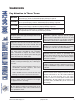
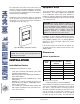
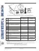
Table A: Basic Data
6
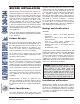
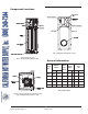
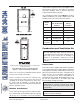
Component Locations
Panels omitted for clarity
Fig. 1: Component Locations – Side
Top panel, blower and gas train omitted for clarity
Fig. 2: Component Locations – Top
Fig. 3: Component Locations – Rear
Model
No.
MBTUH
Input*
Water
Conn.
(NPT)
Gas
Conn.
(NPT)
Vent
Size
(in.)
Max.* Min.* N P Flue Intake
504 500 350 2 1 1 8 6
754 750 525 2 1 1 10 6
1104 1100 770 2-1/2 1-1/4 1 10 6
1504 1500 1050 2-1/2 1-1/4 1 12 8
2004 1999 1400 2-1/2 2 1 14 8
*H7 units only.
California Hot Water Supply, Inc.
(800) 249-7244
6