Aqua Logic Automation and Chlorination Installation Manual for models AQ-LOGIC-PS-4 AQ-LOGIC-PS-8 G LDLINE CONTROLS INC. www.goldlinecontrols.
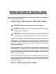
IMPORTANT SAFETY INSTRUCTIONS When using this electrical equipment, basic safety precautions should always be followed, including the following: • READ AND FOLLOW ALL INSTRUCTIONS • ! WARNING: Disconnect all AC power during installation. • ! WARNING: Water in excess of 100 degrees Fahrenheit may be hazardous to your health. • ! WARNING: To reduce the risk of injury, do not permit children to use this product unless they are closely supervised at all times.
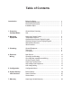
Table of Contents Introduction Before You Begin................................................................... Plumbing Requirements....................................................... Electrical Requirements....................................................... Installation Steps.................................................................... 1 2 2 2 1. Preparing Pool/Spa Water General Water Chemistry..................................................... 3 Salt..............................
Introduction Before You Begin Before installing the Aqua Logic System -Determine that you have everything necessary to complete the installation -Find a suitable mounting location for both the control center and remote keypad -Plan and determine where components will be plumbed -Plan wire runs and wiring connections What’s Included Before attempting to install the Aqua Logic system, check that the following components have been included in the package: Aqua Logic Electronics Unit (2) Temperature sensors
Plumbing Requirements The only special plumbing requirements for the Aqua Logic are the Turbo Cell and flow switch which are typically plumbed after the heater but before the pool/spa return valve. Refer to page 9 for detailed instructions. Electrical Requirements Power must be shut off at the circuit breaker before performing any wiring. Be sure to follow all local and NEC electrical codes. The Aqua Logic is designed to be used as a circuit breaker subpanel for all the pool equipment.
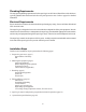
1. Preparing Pool/Spa Water General Water Chemistry Salt is required only if you are using the chlorinator features on the Aqua Logic Control. If you are NOT using the chlorinator, it is recommended that you follow all of the other chemistry recommendations besides salt. Refer to the description of the Aqua Logic configuration menu for information on enabling/ disabling the chlorinator (see pg 19).
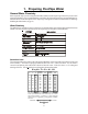
The pool’s chemistry must be balanced BEFORE activating the Aqua Logic’s sanitizing function. NOTE: If the pool does not have new water, add metal remover and non-copper based algaecide to the pool, per manufacturer’s instructions. This ensures a quick, troublefree transfer to the Aqua Logic system. Salt Salt Level Use the chart below to determine how much salt in pounds or (Kgs) should be added to reach the recommended levels.
Pool Sizing Formula Liters Gallons (pool size in meters) (pool size in feet) Rectangular Length x Width x Average Depth x 7.5 Length x Width x Average Depth x 1000 Round Diameter x Diameter x Average Depth x 5.9 Diameter x Diameter x Average Depth x 785 Oval Length x Width x Average Depth x 6.7 Length x Width x Average Depth x 893 Type of Salt to Use It is important to use only sodium chloride (NaCl) salt that is greater than 99% pure.
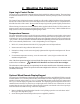
2. Mounting the Equipment Aqua Logic Control Center The Aqua Logic is contained in a raintight enclosure that is suitable for outdoor mounting. The control must be mounted a minimum of 5 ft. (2 meters) horizontal distance from the pool/spa (or more, if local codes require). The Control Center is designed to mount vertically on a flat surface with the knockouts facing downward.
3. See “Electrical Wiring” (page 17) for instructions on running the cable from the Aqua Logic main unit to the remote display/keypad. Pull up on bottom edge to remove cover Optional Wireless Remote Display/Keypad The Aqua Logic Wireless Remote Display/Keypad (Goldline part number AQL-REMOTE-RF-PS-x) must be mounted indoors or in a weather protected area (rain should never hit the display/keypad).
3. Plumbing General Pool Equipment Refer to the following guidelines and the diagram below. 1. Spa should be at or above the level of the pool. For raised spas: Provide a means for the spa to overflow into the pool and install check valves in the spa return and the pool suction (see diagram) to prevent the spa draining while the pool/spa suction and return valves are rotating.
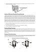
Turbo Cell The Turbo Cell (used for chlorine generation) should be plumbed AFTER the filter and heater. If installed on a pool/spa combination system, the cell should be plumbed BEFORE the pool/spa return valve in order to allow proper chlorination of both the pool and the spa. Refer to plumbing diagram below: 12” min Flow switch before cell Flow switch after cell The cell may be mounted vertically or horizontally, and water can move in either direction through the cell.
4. Electrical Wiring Wireless Base Receiver Connector Remote Display/Keypad Connector “Local” Display 3 Temp Sensor Inputs 2 Heater Outputs 4 Valve Connectors 4 3 2 1 8 High Voltage Relays (4 relays for PS-4 unit) Flow Switch Connector Control Power Input Cell Connector Subpanel N L2 L1 Bonding Lug(s) Ground Bus Bar The Aqua Logic Control Center requires both high and low voltage connections. Low voltage connections will be made to actuators, sensors, remote keypad, etc.
Grounding and Bonding Connect a ground wire from the primary electrical panel to the Aqua Logic ground bus bar. Also ground each piece of high voltage (120 or 240VAC) equipment that is connected to the Aqua Logic control relays or circuit breakers. The Aqua Logic should also be connected to the pool bonding system by an 8AWG (6AWG for Canada) wire. A lug for bonding (2 for Canada) is provided on the outside/bottom of the Aqua Logic enclosure.
High Voltage (120/240V) Pool Equipment All Aqua Logic relays are double pole (they make/break both “legs” of 240V circuits) and are rated at 3HP/30A at 240V (1½HP/30A at 120V). Refer to the diagram below for typical relay wiring: 240 VAC Load Wiring relays for 240 VAC Pool Equipment 120 VAC Load Wiring relays for 120 VAC Pool Equipment 120 VAC Load Wiring GFCB for 120 VAC Pool Equipment ! WARNING: Do not use the Aqua Logic to control an automatic pool cover.
Low Voltage Wiring Valve Actuators The Aqua Logic can control up to four 24V automatic valve actuators. Two of the valve outputs are dedicated to the pool/spa suction (Valve2) and return (Valve1) valves. Valve3 and Valve4 are for general purpose use (solar, water feature, in-floor cleaner, etc.). For installations with solar heating, Goldline offers the AQ-SOL-KIT-xx solar kit that contains a valve, actuator, and extra temperature sensor. The “xx” indicates the valve type from the 3 choices below: -1P 1.
Generic Heaters 1. Wire heater to 120/240V power source per the instructions in the heater manual. The Aqua Logic does NOT control the power going to the heater. 2. Wire the Aqua Logic dry contact heater output per the diagram below. Many internal parts of the heater can get very hot--see the heater manufacturer’s recommendations on the minimum temperature rating for wires. If no guidance is given, use 105°C rated wire. 3. Set any ON/OFF switch on the heater to ON. 4.
Hayward Heaters Refer to the instructions in the heater manual for “2-wire Remote Thermostat” operation under “Remote Control Connections” and the diagram on the following page: 1. 2. 3. 4. 5. 6.
Raypak RP2100 Pool/Spa Heater 1. 2. 3. 4. 5. Turn power off to heater Push the mode button to “spa” mode Set the temperature to the maximum Push the mode button to “OFF” Lastly, plug the prewired connector in the P7 position on the board. ! IMPORTANT: The heater will display “OFF” when it is being remotely controlled by the Aqua Logic. Some homeowners see the “OFF” display and, thinking this is a mistake, change the mode to “POOL” or “SPA” which then disables the remote control by the Aqua Logic.
Temperature Sensors The Aqua Logic utilizes 10K ohm thermistor type sensors. Two sensors (water temperature and air temperature) are included. If the Aqua Logic is being used to control a solar heating system, a third “solar” sensor will be required. The sensors are provided with a 12 ft. cable. If a longer cable is required, contact the Goldline service dept. (921-888-7665) for information on suitable cable types and splices. See Temperature Sensors on page 6 for directions on installing the sensors.
If multiple remote display/keypads are installed: Never connect more than 2 wires to any terminal block. Two remotes can be wired back to the Aqua Logic main unit or the second display/keypad (and third, if applicable) can be “daisy chained” with one display/keypad wired to the next. The maximum wire run from the Aqua Logic main unit to the furthest remote display/keypad is 500 ft (160m).
5. Configuration Setup After plumbing and wiring are complete, the Aqua Logic MUST BE CONFIGURED before attempting to operate. Configuration information is entered at the keypad and “tells” the Aqua Logic what equipment is connected and how each should be controlled. Accessing the Configuration Menu Configuring the Aqua Logic requires that you navigate through the Configuration Menu and input various information.
Logic will turn on the filter pump to circulate the water. If “Pool and Spa” is selected in the Pool/Spa sub-menu (see page 21), the valves will also alternate between the pool and spa every 30 minutes and the filter pump will turn off while the valves are turning. The heater(s) and chlorinator will not operate if freeze protection is the only reason the pump is running. NOTE: Heater1 and Heater2 configuration are identical.
if “Solar” is enabled Solar Priority Disabled > Move to next menu item Toggle between Enabled and Disabled (default) Solar Extend + > Move to next menu item Toggle between Enabled and Disabled (default) Solar Extend + > Solar-Extend Disabled Toggle between Enabled and Disabled (default) Solar + > if “Solar” is enabled Push to access solar options > Move to previous/next configuration menu > Solar Disabled + > Solar Config.
is selected, then the pool/spa suction and return valve actuators should be connected to the Aqua Logic. Pressing the POOL/SPA button on the display/key pad will allow the homeowner to alternate between pool and spa operation.
NOTE: The configuration parameters for all Aux outputs are same as shown below for Aux1. PS-4 models have two Aux outputs: Aux1 and Aux2. PS-8 models have six Aux outputs: Aux1 through Aux6.
Aux1 Interlock If “Enabled”, this feature will override the function (manual on/off, countdown timer, timeclock, selected above and turn the aux1 or aux2 relay off. This forced off condition occurs when: filter pump is off, first 3 minutes of filter pump operation (allows the pump to prime and get water flowing), when the pool/spa suction return valves are in any position other than “pool only”, for 3 minutes after solar turns on (allows air in the solar panels to be purged).
In-Floor Cleaner – the valve switches the water returning to the pool between the in-floor cleaner and the normal return jets which facilitate efficient surface skimming. The valve will operate the in-floor cleaner for the first half of each clock hour and then switch to the jets/ skimming for the last half of the hour.
6. System Startup and Checkout Before Startup Before starting the Aqua Logic for the first time, be sure that the following items have been completed: 1. 2. 3. 4. 5. 6. Pool/spa chemicals are within the recommended levels according to the chart on page 3. Pool/spa salt level is between 2700 – 3400 PPM. Properly rated circuit breakers are installed in the Aqua Logic subpanel. All wiring is performed according to NEC and local codes. The Aqua Logic is properly grounded and bonded.
3. Once the heater is running, you can verify the “heater cooldown” feature (optional - see Configuration Menu/Heater Config.) is operating properly: • Press the “Filter” button once (for 2 speed pumps, this may require 2 pushes of the “Filter” button) • The heater should turn off (“Heater” LED off) and the “Filter” LED will flash to indicated heater cooldown is active.
Limited Warranty—Pool Automation & Chlorination Products 1/1/2004 This warranty statement is applicable to all pool automation and chlorination products manufactured by Goldline Controls, Inc. (Goldline) on or after January 1, 2004. See the appropriate warranty statement for other Goldline products or for pool automation and chlorination products produced prior to January 1, 2004.
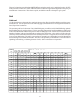
Aqua Logic Programming Flow Chart default menu day and time air/water temperature chlorinator setting salt level settings menu spa heater1 temp (off, 65ºF-104ºF) pool heater1 temp (off, 65ºF-104ºF) spa heater2 temp (off, 65ºF-104ºF) pool heater2 temp (off, 65ºF-104ºF) spa solar temp (off, 65ºF-104ºF) pool solar temp (off, 65ºF-104ºF) superchlorinate (on/off) spa chlorinator setting (0-100%) pool chlorinator setting (0-100%) day and time display light (always on/60 sec) teach wireless remote wireless chan