INSTALLATION & OPERATING INSTRUCTIONS Heat Pump Pool & Spa Heater Professional Series PS10353ti-E-HC PS10354ti-E-HC PS10355ti-E-HC R C LI S TED US FOR YOUR SAFETY: Do not store or use gasoline or other flammable vapors and liquids or other combustible materials in the vicinity of this or any other appliance. To do so may result in an explosion or fire.
Rev. 2 reflects the following: Changes to: Installation Considerations on pages 6-7, Hurricane Tie Down Requirements diagram on page 8, Table C on page 14, Wiring diagrams on pages 19-21. Additions: None. Deletions: None.
Water Chemistry (Corrosive water voids all warranties) For your health and the protection of your pool equipment, it is essential that your water be chemically balanced. The following levels must be used as a guide for balanced water. Recommended Level(s) Water Temp. (Deg. F) pH Total Alkalinity (PPM) Calcium Hardness (PPM) Salt (PPM) Free Chlorine (PPM)* Total Dissolved Solids (PPM) Fiberglass Pools Fiberglass Spas Other Pool & Spa Types 7.3 to 7.4 7.3 to 7.4 7.6 to 7.
CONTENTS Water Chemistry Warnings Pay Attention to These Terms Introduction Installation Considerations Electrical Connections Water Connections Pressure Drop Controls Operating Instructions To Select Pool or Spa Mode To Increase the Desired Water Temperature (Pool or Spa Mode) To Lower Desired Water Temperature (Pool or Spa Mode) To Select Temperature in °C or °F Heat/Cool Operation System Start-Up Seasonal Start-Up or Annual Check Summer Shutdown Freeze Protection System Drain-Down Continuous Pump Operat
Warnings DANGER: WARNING: CAUTION: NOTE: — Pay Attention to These Terms Indicates the presence of immediate hazards which will cause severe personal injury, death or substantial property damage if ignored. Indicates the presence of hazards or unsafe practices which could cause severe personal injury, death or substantial property damage if ignored. Indicates the presence of hazards or unsafe practices which could cause minor personal injury or product or property damage if ignored.
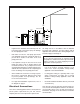
Introduction Installation Considerations WARNING: Do not install the unit within 3 ft of fossil fuel burning heaters. Air intake along the sides of this heat pump pool heater could disturb the combustion process of the unit, and could cause damage or personal injury. • Mount the unit on a level, sturdy base, preferably a concrete slab or blocks. The size of the base should be at least 3 ft by 3 ft. • You must install the 4 black rubber sound isolation pads (each 2 inches square) that ship with the unit.
60” MIN 3 FT MIN GAS HEATER • • • • • AIR FLOW OUT 12” MIN AIR FLOW IN AIR FLOW IN Fig. 1: Installation Clearances Irrigation water should be directed away from the heat pump pool heater-water spray can damage the heat pump pool heater. All wiring must be in accordance with the National Electrical Code, NFPA No. 70, latest edition, and all applicable state and local codes. Wiring diagrams are located on pages 19 through 21.
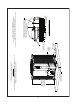
SEE HIGH WIND LOAD RESTRAINT DETAIL 1 COVERED UNIT HEIGHT BETWEEN 37-1/2” - 49-3/4” NOT INCLUDING ISOLATOR PADS GREATER THAN OR EQUAL TO 4” THICK SOLID CONCRETE 3000 P. S. I. OR GREATER LOAD RATING PAD LENGTH GREATER THAN OR EQUAL TO UNIT LENGTH +6” PAD WIDTH GREATER THAN OR EQUAL TO UNIT WIDTH +6” PAD SPECIFICATION: THIS DRAWING USED AS A GRAPHICAL REPRESENTATION ONLY AND IT MAY NOT APPEAR EXACTLY LIKE YOUR SPECIFIC UNIT. 2-1/2” MIN. SPACING TYP.
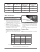
Model No. VAC - Phase - Hz Minimum Circuit Ampacity (A) Maximum Breaker Size (A) 10353 208/230 - 3 - 60 42.0 70 10354 460 - 3 - 60 26.0 40 10355 380 - 3 - 60 29.0 45 Table A: Typical System Electrical Power Requirements Water Connections CAUTION: The heat pump pool heater inlet and outlet connections are NOT interchangeable. They must be connected as instructed below. WATER IN 1. Connect the heat pump pool heater in the return water line between the filter and the pool/spa.
Operating Instructions WARNING: Install a check valve and/or a Hartford loop AFTER the heat pump pool heater and BEFORE any chlorinating devices. Install any automatic chemical feeders AFTER the heat pump pool heater. Improper installation of any type of automatic chemical feeders can result in serious damage to, or premature failure of, the heat pump pool heater and will void the heat pump pool heater warranty.
Heat/Cool Operation Seasonal Start-Up or Annual Check The Raypak Professional models come standard with heat/cool operation. The heat/cool model is designed to both heat and cool the pool. To select heat or cool mode, push the SET key until H/C is displayed. Press the DOWN arrow key to select heating (hea), or the UP arrow key to select cooling (col). Set the desired setpoint temperature as described earlier in this manual.
Freeze Protection Cabinet Care (optional) If the unit is installed in a location subject to freezing conditions, it is important to protect the water circuit from freezing, just as should be done for the pump and filter. The stainless steel cabinet is designed for harsh outdoor use and requires little care. However, you can clean it if you wish. 1. Turn the unit circuit breaker or disconnect switch to OFF. Wash the cabinet with soap and water. WARNING: Shut OFF electricity to the unit before cleaning.
• • How long has the unit been operating? During initial pool heating in cold weather, it may require a week to elevate the water temperature to a comfortable level. Normally, it takes about 4 days. NOTE: The heat pump pool heater will not run when the Remote position is selected on the Pool/Spa selector switch and there is no remote control system attached. How many hours per day is the unit operating? Remember that the heat pump pool heater only operates while the pool pump is running.
Time Clock Adjustment Verify that the time clock is set to permit the unit to run long enough to heat properly. Fault Code OFF LP LP3 HP HP6 PSd Meaning of Code The desired programmed temperature point is lower than 50°F (10°C). There is a shortage of refrigerant gas in the unit or a faulty low pressure control, or the ambient air is too cold. The unit has encountered 3 LP faults within the same call for heat and shut down the unit for protection. If this occurs, you should call for service.
WATER IN (FROM POOL OR SPA) FILTER CHECK VALVE CHEMICAL INTRODUCTION WATER OUT (TO POOL OR SPA) Plumbing Diagrams Fig. 6: For systems with pumps of less than 2 HP (under 80 gpm), no external bypass is required. Connections are 2-inch unions. Plumb the heat pump pool heater AFTER the filter and BEFORE any chlorinators.
WATER OUT (TO POOL OR SPA) WATER IN (FROM POOL OR SPA) FILTER CHECK VALVE CHEMICAL INTRODUCTION Fig. 7: For systems with pumps of 2 HP or greater (over 80 gpm), an external bypass is required. Adjust the bypass valve to divert a minimum of 40 gpm through the heat pump pool heater. Connections are 2-inch unions. Plumb the heat pump pool heater AFTER the filter and BEFORE any chlorinators.
Fig.
Fig.
Wiring Diagram 208V/230V 3Ph, 60Hz Models 19
Wiring Diagram 460V 3Ph, 60 Hz Models 20
Wiring Diagram 380V 3Ph, 60 Hz Models 21
Installing a Remote Control Device Wiring For a 2-wire control, use the TOTAL and COMMON connections on the heat pump pool heater wiring block. For a 3-wire control, use the COMMON, SPA and POOL connections on the heat pump pool heater wiring block. Fig. 11: Heater Wiring Block Heater Settings 1. Make sure the heater is disabled on the remote control device. Then, push the SET key until POL is displayed. Push the DOWN arrow key until OFF is displayed.
Raypak, Inc., 2151 Eastman Avenue, Oxnard, CA 93030 (805) 278-5300 Fax (805) 278-5468 Heat Pump Service 1-800-260-2758 Litho in U.S.A.