
Operating instructions

9
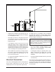
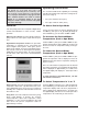
Water Connections
1. Connect the heat pump pool heater in the return
water line between the filter and the pool/spa. See
the Plumbing Diagrams beginning on page 15.
2. Connect the filter outlet to the fitting marked
WATER IN at the bottom front of the unit.
3. Connect the fitting marked WATER OUT to the
return piping to the pool/spa. Unit inlet/outlet con-
nection fittings are 2-inch PVC unions.
Water connections from the unit to the main return
line can be PVC pipe or flexible pipe approved for
the purpose and, in either case, should be at least
equal in size to the main pool/spa circulation pip-
ing.
4. In cold weather (freeze zone) areas, shutoff valves
(ball or gate type) must be installed at the unit inlet
and outlet to facilitate service and cold weather
drain-down.
5. Operate the pump and check the system for leaks.
Pressure Drop
For system pressure drop information, refer to Table B
below.
CAUTION: The heat pump pool heater inlet and
outlet connections are NOT interchangeable. They
must be connected as instructed below.
Fig. 2: Water Connections
WATER IN
WATER OUT
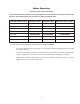
Table B: Pressure Drop Across Heat Pump Pool Heater
Flow
(gpm)
Pressure Drop (psi)
10353HC 10354HC 10355HC
30 10 10 10
40 10 10 10
50 11 11 11
60 12 12 12
70 13 13 13
80 14 14 14
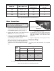
Model No. VAC - Phase - Hz
Minimum Circuit
Ampacity (A)
Maximum Breaker
Size (A)
1
0353
2
08/230 - 3 - 60
4
2.0
7
0
1
0354
4
60 - 3 - 60
2
6.0
4
0
10355 380 - 3 - 60 29.0 45
Table A: Typical System Electrical Power Requirements
Note: Multiply the pressure drop in psi by 2.3067 to yield the pressure drop in Ft. H
2
O Head (TDH).