
Instructions / Assembly

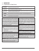
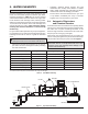
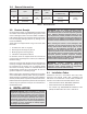
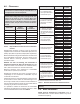

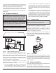
Table Of Contents

8
4.2. Clearances
AA
AVERTISSEMENT: Cet appareil doit être installé
conformément au National Fuel gas Code ANSI Z223.1, et
aux exigences de l’autorité competente.
NOTE: The heater should not be located in an area where
possible water leakage will result in damage to the area
adjacent to the heater or to the structure. When such
locations cannot be avoided, it is recommended that a
suitable drain pan, with adequate drainage, be installed
under the heater. The pan must not restrict combustion
air ow.
Heater Side
Outdoor
Installations
Indoor
Installations
Top* Unobstructed 30" (76.2 cm)
Front 24" (61 cm) Alcove
Vent N/A 6" (15.2 cm)
Back 12" (30.5 cm) 12" (30.5 cm)
Right Side 6" (15.2 cm) 6" (15.2 cm)
Left Side 6" (15.2 cm) 6" (15.2 cm)
*Clearance from top of vent terminal.
Table C. Required Minimum Clearances from Combustible
Surfaces
Dégagements minimaux à assurer entre les parois de
l”appareil et les contructions combustibles: 6po (15.2 cm)
(côtés), 12po (30.5 cm) (arrière) et 30po (76.2 cm) (dessus).
When installed according to the listed minimum clearances
from combustible construction, the pool heater can be
serviced without removing permanent construction
around the heater.
However for ease of servicing, we recommend a
clearance of at least 18" (45.7 cm) on the rear. This will
enable the heater to be serviced in its installed location,
that is, without movement or removal of the heater.
Minimum clearance from drafthood to combustible
construction 6" (15.2 cm) from the vent.
Degagement minimal de 6 po (15.2 cm) requis entre le
coupe-tirage et une construction combustible. 2 po du
conduit de raccordement.
Clearances less than recommended may require removal
of the heater to service either the heat exchanger or the
burner tray. In either case, the heater must be installed in a
manner that will enable the heater to be serviced without
removing any structure around the heater.
It is possible to reduce the clearances to combustible
surfaces by protecting these surfaces as shown in table
10.2.3 of the National Fuel Code. See Table D.
Description Location
Distance
in. (mm)
a. 3-1/2" (89 mm) thick
masonry walls without
ventilated air space
Back 9 (229)
Right 9 (229)
Left 9 (229)
Vent 5 (127)
Indoor Top 39 (991)
Outdoor Top Unobstructed
b. 1/2" (13 mm)insulation
board over 1" (25 mm)
glass ber or mineral
wool batts
Back 6 (152)
Right 6 (152)
Left 6 (152)
Vent 3 (76)
Indoor Top 30 (762)
Outdoor Top Unobstructed
c. 0.024 sheet metal over
1" (25 mm) glass ber
or mineral wool batts
reinforced with wire on
rear face with ventilated
air space
Back 4 (102)
Right 4 (102)
Left 4 (102)
Vent 3 (76)
Indoor Top 24 (610)
Outdoor Top Unobstructed
d. 3-1/2" (89 mm) thick
masonry wall with
ventilated air space
Back 6 (152)
Right 6 (152)
Left 6 (152)
Vent 6 (152)
Indoor Top 39 (991)
Outdoor Top Unobstructed
e. 0.024 sheet metal with
ventilated air space
Back 4 (102)
Right 4 (102)
Left 4 (102)
Vent 2 (51)
Indoor Top 24 (610)
Outdoor Top Unobstructed
f. 1/2" (13 mm) thick
insulation board with
ventilated air space
Back 4 (102)
Right 4 (102)
Left 4 (102)
Vent 3 (76)
Indoor Top 24 (610)
Outdoor Top Unobstructed
g. 0.024 sheet metal with
ventilated air space over
0.024 sheet metal with
ventilated air space.
Back 4 (102)
Right 4 (102)
Left 4 (102)
Vent 3 (76)
Indoor Top 24 (610)
Outdoor Top Unobstructed
h. 1" (25 mm) glass ber
or mineral wool batts
sandwiched between
two sheets 0.024 sheet
metal with ventilated air
space
Back 4 (102)
Right 4 (102)
Left 4 (102)
Vent 3 (76)
Indoor Top 24 (610)
Outdoor Top Unobstructed
Derived from National Fuel Gas Code, Table 10.2.3
Table D. Reduction of Clearances to Protected Surfaces
FLOORING: This heater can be installed on combustible
ooring.
4.3. Base Installation
Heater must be mounted on a level base, such as
cementable slab or cement blocks. Heaters may not be
installed on carpeting.